background image

T5e

ec-H2O

Kit

INSTALLATION INSTRUCTIONS --

Continued

Page 4 of 9

KIT NO. 9006828

9006829 Rev. 00 (12--09)

Tennant Company

Customer Service: (800) 553--8033 or (763) 513--2850

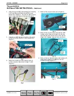
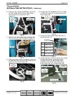
3. Connect the routed

ec--H2O

harness wires to the

LED light (GRAY to RED, GRN to GRN and BLK to

BLK) (Figure 18).

ec--H2O

LED Light

ec--H2O

Harness

Wires

Fig. 18

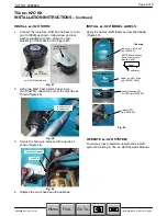
4. Remove the lower control panel from console

(Figure 19).

Fig. 19

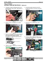
5. Remove the components from the lower panel

(take

note of wire connections before removing)

. Using

new lower panel [p/n 1024111] and label

[p/n 1050011], re--install components (Figure 20).

Lower Panel [p/n 1024111]

Label [p/n 1050011]

Fig. 20

6. Install the

ec--H2O

on/off switch [p/n 130787] as

shown (Figure 21).

ec--H2O

on/off Switch

[p/n 130787]

Take note of

switch orientation

Fig. 21

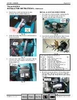
6. Route the remaining console wires from the

ec--H2O

wire harness to the lower control panel

(Figure 22).

ec--H2O

Harness

Wires

Fig. 22

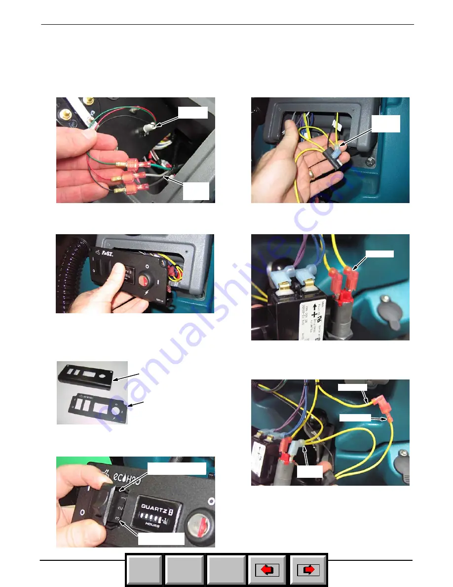
7. Disconnect wire 14 yellow from key switch

(Figure 23).

14 Yellow

Fig. 23

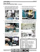
8. Connect

ec--H2O

harness wires 94/94A yellow to

key switch as shown (Figure 24). Connect 94B

yellow to wire 14 yellow.

94/94A

Yellow

94B Yellow

14 Yellow

Fig. 24

Home

Find...

Go To..

Summary of Contents for T5e ec-H2O 9006828

Page 1: ...ead assembly disconnect the battery cables Disk Model shown Fig 1 4 Remove the batteries from the machine Figure 2 FOR SAFETY When handling batteries wear pro tective gloves and eye protection Avoid c...

Page 2: ...circuit breaker box Figure 7 ec H2O Harness Connector Fig 7 6 Route the following ec H2O harness wires to control console as described in steps 7 and 8 Figure 8 To LED Light To ec H2O on off Switch Fi...

Page 3: ...circuit breaker box as shown Figure 14 Harness Wires C To Control Console Fig 14 12 Replace circuit breaker box cover Figure 15 Fig 15 INSTALL THE ec H2O CONTROL CONSOLE COMPONENTS 1 Remove the upper...

Page 4: ...removing Using new lower panel p n 1024111 and label p n 1050011 re install components Figure 20 Lower Panel p n 1024111 Label p n 1050011 Fig 20 6 Install the ec H2O on off switch p n 130787 as show...

Page 5: ...ue 30 Tan Fig 27 12 Replace the lower and upper control panels INSTALL THE ec H2O MODULE 1 Cut the two ec H2O module hoses to the specified length and set the DIP switch settings accordingly Figure 28...

Page 6: ...t Fig 33 2 Assemble the pump assembly as shown Figure 34 Use a thread sealer tape on all fittings 2 1 3 4 6 5 7 10 12 11 9 8 Fig 34 Ref p n Description Qty 1 1042495 Pump Soltn Ele 24Vdc 35psi 1 2 102...

Page 7: ...8 Install clamp p n 69234 and route the two ec H2O module hoses as shown Figure 39 Module Hoses Clamp p n 69234 Fig 39 9 Cut the 4 ft braided hose p n 578227000 into the specified hose lengths as des...

Page 8: ...from step 9 Figure 43 From ec H2O Pump ec H2O Solution Hose Assembly Fig 43 13 Connect wires 13T BLK 99 WHT from the routed ec H2O wire harness to the pressure switch as shown Figure 44 Wire 13T Blk...

Page 9: ...n 1034731 attach the horn to the machine as shown Figure 48 2 M6x1 00x16 Sems Screws Fig 48 3 Secure the horn wire harness with wire tie as shown Figure 49 Wire Tie Horn Wire Harness Fig 49 4 Replace...

Reviews: