Page 5 of 9
KIT NO. 9006828
T5e
ec-H2O
Kit
INSTALLATION INSTRUCTIONS --
Continued
9006829 Rev. 00 (12--09)
Tennant Company
Customer Service: (800) 553--8033 or (763) 513--2850
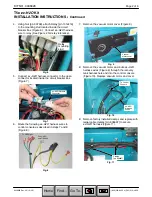
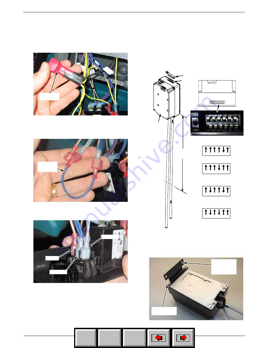
9. Connect diode [p/n 222290] to the
ec--H2O
harness
as shown (Figure 25).
Diode
[p/n 222290
Fig. 25
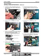
10. Within the lower control console wiring, locate and
remove Blue Jumper Wire 36 from wires 8/8A Gray
and 6/16 Blue and discard (Figure 26).
Blue
Jumper
Wire 36
Fig. 26
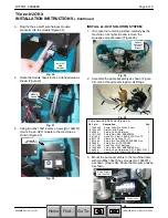
11. Connect wires 8/8A Gray, 6/16 Blue and 30 Tan to
the
ec--H2O
on/off Switch as shown (Figure 27).
8/8A Gray
6/16 Blue
30 Tan
Fig. 27
12. Replace the lower and upper control panels.
INSTALL THE
ec- H2O
MODULE:
1. Cut the two
ec--H2O
module hoses to the specified
length and set the DIP switch settings accordingly
(Figure 28). Install the DIP switch grommet
[p/n 1054776].
26 in
66 cm
Cut
DIP Switch Setting
32”/800mm
Cylindrical Model
24”/600mm Disk Model
26”/650mm
Cylindrical Model
28”/700mm &
32”/800mm Disk Models
1 2 3 4 5 6
1 2 3 4 5 6
1 2 3 4 5 6
1 2 3 4 5 6
Grommet [p/n 1054776]
Top View of Module
DIP
Switch
ec--H2O
Module
[1048395]
Fig. 28
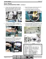
2. Using two m6x1.00x16 sems screws [p/n 1034731],
attach the
ec--H2O
module mounting bracket
[p/n 1045965] to the
ec--H2O
module as shown
(Figure 29).
Module
Mounting
Bracket
[p/n 1045965]
Screw (2)
[p/n 1034731]
Fig. 29
Home
Find...
Go To..


