T5e
ec-H2O
Kit
INSTALLATION INSTRUCTIONS --
Continued
Page 8 of 9
KIT NO. 9006828
9006829 Rev. 00 (12--09)
Tennant Company
Customer Service: (800) 553--8033 or (763) 513--2850
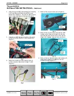
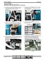
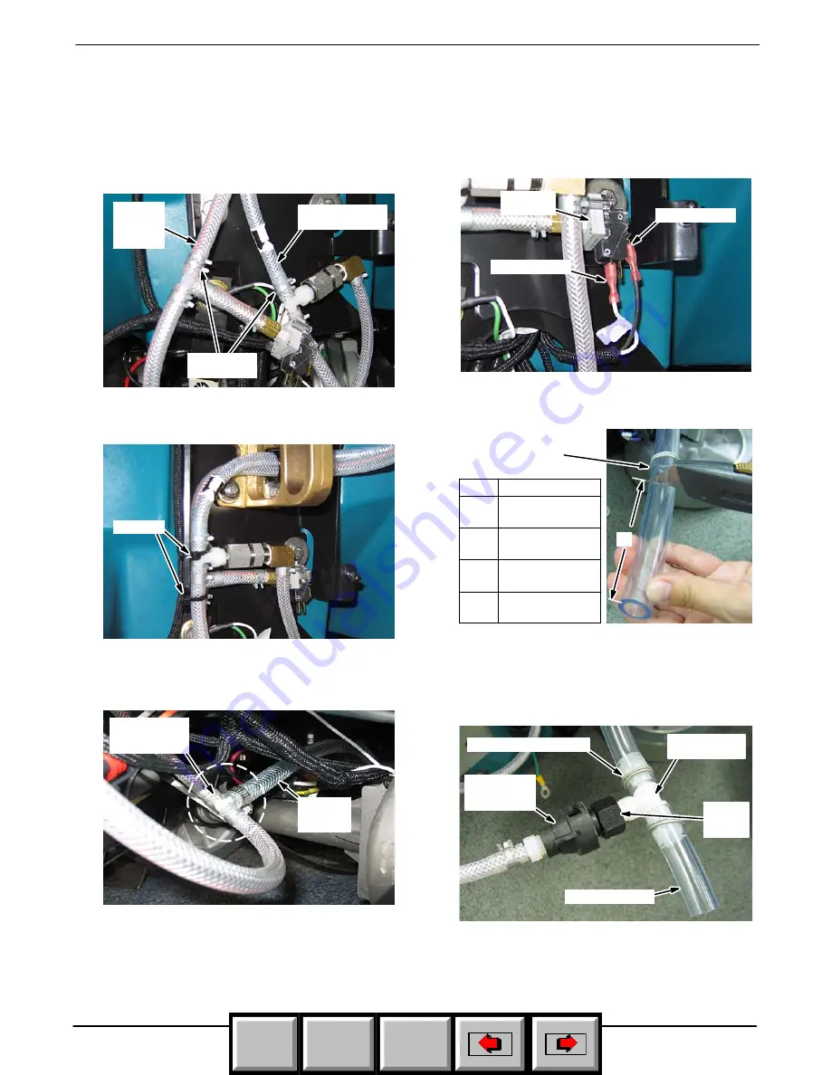
10. Using two hose clamps [p/n 603654], connect the
ec--H2O
module hoses to the
ec--H2O
solution
hose assembly (from step 9) as shown
(Figure 41).
ec--H2O
Module
Outlet Hose
ec--H2O
Module
Intake
Hose
Clamp (2)
[p/n 603654]
Fig. 41
11. Secure the
ec--H2O
solution hose assembly with
two wire--ties [p/n 130773] as shown (Figure 42).
Wire--tie
Fig. 42
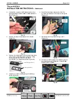
12. Using a wormdrive clamp [p/n 54333], connect the
ec--H2O
pump hose to the
ec--H2O
solution hose
assembly (from step 9) (Figure 43).
From
ec--H2O
Pump
ec--H2O
Solution Hose
Assembly
Fig. 43
13. Connect wires 13T BLK/99 WHT from the routed
ec--H2O
wire harness to the pressure switch as
shown (Figure 44).
Wire 13T Blk
Wire 99 Wht
Pressure
Switch
Fig. 44
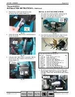
14. Cut the machine’s solution tank outlet hose as
specified (Figure 45).
Solution Tank
Outlet Hose
A
A
=
Scrub Head Type
2”
600mm Disk
5.1cm
3”
700mm Disk
7.6cm
4”
800mm Disk
10.1cm
15.5” Cylindrical Brush
39.4cm
Fig. 45
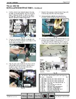
15. Using T--fitting [p/n 1010791] and two wire clamps
[p/n 607776], connect the quick disconnect
connector from the
ec--H2O
solution hose
assembly to the solution tank outlet hose as
shown (Figure 46). Use a thread sealer tape.
To Scrub Head
Quick
Disconnect
Connector
T--fitting
[p/n 1010791]
Clamp (2) [p/n 607776]
Thread
Sealer
Tape
Fig. 46
Home
Find...
Go To..


