background image

9

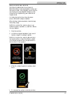
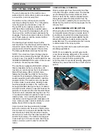
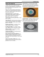
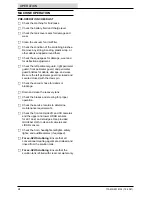
T7AMR 9018134 (12-2021)

 SAFETY  

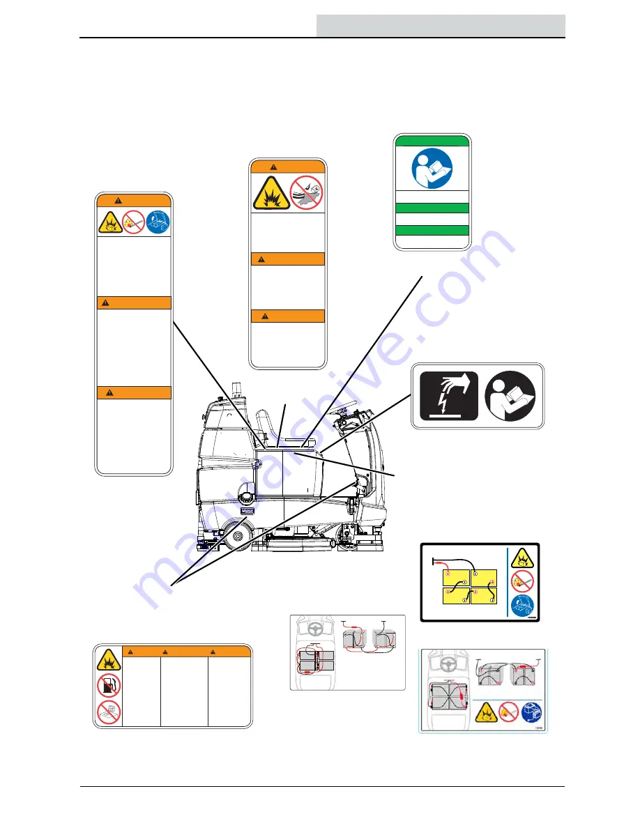
The following safety labels are mounted on the 

machine in the locations indicated. Replace 

damaged/missing labels.

11535

WARNING

Los materials 
inflammables o metales 
reactivos pueden 
causer explosions o 
incendios.
No los recoja.

Les mat

ériaux

inflammables ou les 

taux r

éactifs peuvent 

causer une explosion 
ou un incendie. 
Ne les ramassez pas.

AVERTISSEMENT

ADVERTENCIA

Flammable materials 
or reactive metals 
can cause explosion 
or fire. 
Do not pick up. 

Flammable
materials
can cause 
explosion or 
fire.
Do not use 
flammable
materials in 
tank.

Los materiales 
inflamables
pueden
provocar
explosiones
o incendios. 
No utilice 
materiales
inflamables en 
el depósito(s).

Les matières
inflammables
peuvent causer 
une explosionou 
un incendie. 
N’utilisez pas de 
matières
inflammables
dans le(s) 
réservoir(s).

25815

AVERTISSEMENT

A

I

C

N

E

T

R

E

V

D

A

G

N

I

N

R

A

W

27464

Read manual before 
operating machine.

Lisez le manuel avant 
d’utiliser la machine.

Lea el manual antes de 
operar la m

á

quina.

FOR SAFETY

POUR VOTRE SECURITE

PARA SEGURIDAD

WARNING LABEL - 

Batteries emit  

hydrogen gas.  

Explosion or fire can 

result. Keep sparks 

and open flame away. 

Keep covers open 

when charging.

Located on seat panel.

WARNING LABEL - 

Flammable materials 

or reactive metals can 

cause explosion or 

fire. Do not pick up.

Located on 

seat panel.

FOR SAFETY LABEL -  

Read manual before 

operating machine.

Located on seat panel.

FOR SAFETY LABEL - 

Electrical components, use 

grounding strap before 

opening panel.

Located on electrical panel 

under the seat.

WARNING LABEL - Flammable 

materials can cause explosion 

or fire. Do not use flammable 

materials in tank

Located under the solution fill 

port and next to foot pedals.

Batteries emit
hydrogen gas.
Explosion or fire can 
result.
Keep sparks and
open flame away.
Keep covers open
when charging.

11513

AVERTISSEMENT

WARNING

ADVERTENCIA

Les batteries émettent
de l’hydrogène. 
Ce gaz est susceptible
d’exploser ou de 
s’enflammer.
Evitez toute étincelle et
toute flamme nue à
proximité des batteries.
Laissez les capots 
ouverts pendant la 
mise en charge.

Las baterías emiten
hidrógeno gaseoso.
Existe peligro de
incendio o explosión.
Mantenga chispas y
llamas alejadas de 
la máquina.
Mantenga las tapas 
abiertas durante la
operación de carga.

32482

WARNING LABEL - Batteries 

emit hydrogen gas. Explosion 

or fire can result. Keep sparks 

and open flame away. Keep 

covers open when charging

Located on bottom of 

seat panel.

Lead Acid batteries

TPPL batteries

1257380

(4) 24V Lithium-Ion

Lithium-ION batteries

Summary of Contents for T7AMR

Page 1: ...ber Operator Manual 9018134 Rev 05 12 2021 9018134 North America International For the latest Parts Manuals and other language Operator Manuals visit www tennantco com manuals Hygenic Fully Cleanable...

Page 2: ...anuals PROTECT THE ENVIRONMENT Please dispose of packaging materials used components such as batteries and fluids in an environmentally safe way according to local waste disposal regulations Always re...

Page 3: ...ennant Company Additional training materials may be provided as to the intended use of the T7AMR Scrubber and it should only be used in accordance with such training Use the machine in approved enviro...

Page 4: ...The Machine Robotic Mode Only 25 Scrubbing Manual Mode 26 Double Scrubbing 27 Water Pickup Mode No Scrubbing 28 Scrubbing Robotic Mode 29 Establish Home Markers 29 Logging Into Brainos 30 Changing Re...

Page 5: ...7 Adjusting Rear Squeegee Blade Deflection 87 Skirts And Seals 88 Scrub Head Floor Skirt 88 Left Perimeter Guard Right Perimeter Guard And Front Perimeter Guard 88 Recovery Tank Seal 89 Solution Tank...

Page 6: ...With brake disabled Without filters in place or with clogged filters If it is not in proper operating condition In areas where flammable vapors liquids or combustible dusts are present In outdoor are...

Page 7: ...ple are present in accordance with standard floor cleaning practices Follow site safety guidelines concerning wet floors 5 Before leaving or servicing machine Stop on level surface Turn off machine an...

Page 8: ...re battery in hazardous environment electrically charged humidity extreme temperatures and magnetic fields Do not expose battery to flame or plasma Do not disassemble or mistreat battery Do not tear s...

Page 9: ...away Keep covers open when charging Located on seat panel WARNING LABEL Flammable materials or reactive metals can cause explosion or fire Do not pick up Located on seat panel FOR SAFETY LABEL Read ma...

Page 10: ...l panel G Recovery tank H Recovery tank cover I Flashing light J Operator seat K Batteries L Battery charging connector M Solution tank front cover N Solution tank O Sensor panel P Brake pedal Q Prope...

Page 11: ...C 1 Step button D Horn button E Brush pressure button F Brush pressure indicator lights G Solution flow indicator lights H Solution flow button I Vacuum fan squeegee button J ec H2O system indicator l...

Page 12: ...ORS A Sensors Upper LIDAR B Signal lights Front C Sensors Front 2D camera D Sensors Front 3D camera E Sensors Side 2D camera located on each side of machine F Sensors Side 3D camera located on each si...

Page 13: ...the squeegee blade needs adjustments see ADJUSTING REAR SQUEEGEE BLADE DEFLECTION section of this manual INSTALLING BRUSHES PADS To install the brushes or pad see REPLACING DISK SCRUB BRUSHES OR PAD D...

Page 14: ...t is time to replace cartridge FILLING THE SOLUTION TANK FOR SAFETY Before leaving or servicing machine stop on level surface turn off machine and remove key The machine is equipped with a fill port a...

Page 15: ...scrubbing Then set the preferred brush pressure and solution flow settings NOTE The machine does not save solution flow and brush pressure settings for a robotic route as cleaning needs may change Ad...

Page 16: ...ns the solution flow level should be set to a higher setting middle or top lights Travel speed and floor conditions will affect scrubbing performance With the 1 Step button activated press the Solutio...

Page 17: ...the machine clockwise to disengage the emergency stop function The Emergency Stop Button Released screen appears on the UI touchscreen immediately after the Emergency Stop button is disengaged Touch...

Page 18: ...obotic route or pause an in process robotic route When a saved navigation route is selected on the UI touchscreen the blue start pause button flashes When pressed to start the route in robotic mode th...

Page 19: ...USER INTERFACE UI TOUCHSCREEN The User Interface UI touchscreen located to the left of the steering wheel The UI touchscreen provides a system login screen access to all the machine robotic operation...

Page 20: ...arging See BATTERIES in the MAINTENANCE section ROC ROBOT OPERATIONS CENTER BrainOS Software The BrainOS software provides access to the Brain Corp Robotic Operations Center also known as the ROC The...

Page 21: ...n of BrainOS software installed When the New Update Available screen displays follow these steps NOTE Do not drive the machine when a new software update is available or while the software is being up...

Page 22: ...eaches the perimeter of an area and the machine determines the best route to complete cleaning the area The UI touchscreen allows an operator to teach a new cleaning route run an existing cleaning rou...

Page 23: ...of floor finish to prepare the floor for recoating Scrubbing pad Blue For medium to heavy duty scrubbing Removes dirt spills and scuffs Buffing pad Red For light duty scrubbing without removing floor...

Page 24: ...d wear Be sure the left perimeter guard is closed and secured closed with the clevis pin F Check the vacuum hose for debris or blockage F Drain and clean the recovery tank F Check the brakes and steer...

Page 25: ...erating and people are present in accordance with standard floor cleaning practices Follow site safety guidelines concerning wet floors See Autonomous Navigation Software End User License Agreement EU...

Page 26: ...rgents restorers may cause failure to the ec H2O solution system Drain rinse and refill solution tank with cool clean water before operating the ec H2O system 4 Place the directional switch in the dir...

Page 27: ...ouble scrubbing is available in Manual Mode only Do Not operate the machine on an autonomous cleaning route with the squeegee in the raised double scrub position For heavily soiled areas use the doubl...

Page 28: ...WARNING Flammable materials or reactive metals can cause an explosion or fire Do not pick up WATER PICKUP MODE NO SCRUBBING The machine can be used to pick up water or non flammable liquid spills with...

Page 29: ...mapped areas where more than six cleaning routes are needed Establish a unique home marker for each floor of a multi level building Install home markers in a permanent location on an open wall or colu...

Page 30: ...1 Turn the ON OFF key switch on Allow the BrainOS to start up approximately 1 minute 2 Once the BrainOS loads the UI touchscreen displays a series of maintenance reminders 3 Read and perform the main...

Page 31: ...et to display a variety of languages English is the default language 1 Upon successful PIN Personal Identification Number entry the UI touchscreen displays the main menu Touch SETTINGS 2 Touch LANGUAG...

Page 32: ...eeping alert every five seconds while running in autonomous mode 1 Upon successful PIN Personal Identification Number entry the UI touchscreen displays the main menu Touch SETTINGS 2 Touch Autonomous...

Page 33: ...UI touchscreen will display an error message with messages how to resolve NOTE A flashlight can be used in dark and low light areas to help the machine see and scan the home marker NOTE Do not stand...

Page 34: ...ing the machine a new route If a route is taught in an area with obstructions that are later removed the machine will not clean the areas where the obstructions were previously located Avoid teaching...

Page 35: ...ed home marker 7 Touch one of the available routes to select NOTE In the above screen routes A through D are already being used for robotic routes Route E is available for a new route NOTE If no route...

Page 36: ...TE Do not teach the machine routes that include driving into an elevator or automatic doors The machine can save stop and honk points along the saved route for auto playback when the saved route is ru...

Page 37: ...orner NOTE Avoid narrow spaces The machine requires a width of 48 in 1220 mm to navigate aisles and between displays FOR SAFETY While machine is operating in robotic mode only scrub flat hard surfaces...

Page 38: ...o teach the cleaning route NOTE If the machine reads an incorrect home location an error will display along with a message instructing what home location to go to 17 When the route is successfully sav...

Page 39: ...lete To ensure only the on site operator receives alerts from the ROC only one phone can be paired to the ROC to receive status alerts A paired phone number is automatically discarded when the machine...

Page 40: ...e is in the lowered position for scrubbing Do Not operate the machine on an autonomous cleaning route with the squeegee in the raised double scrub position Lower the squeegee if it is in the raised do...

Page 41: ...iefly displayed followed by a list of all existing routes for the scanned home marker 6 Select the cleaning route s to be run The cleaning routes will operate continuously in the order they are select...

Page 42: ...tings for a robotic route as these needs may change from day to day Determine cleaning requirements for the area s being cleaned and adjust solution flow and brush pressure settings as necessary 10 Re...

Page 43: ...n Route s will repeat until cancelled appears on the screen 14 Select the loop button again to cancel running the route s multiple times A screen stating Repeat Off Route s will run once appears on th...

Page 44: ...and squeegees 20 Press the blue start pause button to resume the route in robotic mode Observe scrubbing performance to ensure that all components are functioning properly 21 As the machine runs the...

Page 45: ...an environmental factor such as a reflection causing the machine to sense an obstruction in the cleaning path For help resolving the issue contact customer service and provide the home marker number r...

Page 46: ...the cleaning history The home marker number route time the route was run and how long it took the machine to run the route are displayed next to the home marker symbol The date the route was run appe...

Page 47: ...splays the main menu Touch LEARN 2 Select the desired video from the list of videos 3 Touch BACK to return to the main menu ASSIST MESSAGES DURING ROBOTIC OPERATION When an assist message is triggered...

Page 48: ...ed home location to view the routes available to be edited at that location NOTE If the machine is programmed for multiple home locations the home locations will be listed in chronological order start...

Page 49: ...Enter a name for the saved route NOTE Route labels can have a maximum of 15 characters 8 Touch REMOVE LABEL to remove an assigned name to an existing route NOTE When a saved route label is removed th...

Page 50: ...ed by accident it must be re taught see TEACHING A NEW ROUTE NOTE Touch CANCEL to cancel the route deletion and return to the list of routes 11 All existing routes for the home location are displayed...

Page 51: ...ve the machine to a solution disposal drain 2 Turn the machine ON OFF key switch off FOR SAFETY Before leaving or servicing machine stop on level surface turn off machine and remove key 3 Tilt the ope...

Page 52: ...ery tank drain hose cap and mount the drain hose back onto the mounting clip after the tank is drained 8 Remove and clean the vacuum fan filter Clean the filter with a damp cloth or low pressure water...

Page 53: ...ecovery tank forward to close the solution tank 14 Unhook the seat latch and lower the operator seat 15 Clean the front of the solution tank through the front access port located under the front solut...

Page 54: ...ause and remedy for the alert If the machine has to restart due to an alert that stopped it observe scrubbing performance to ensure that all components are functioning properly Alert s Cause s Symbol...

Page 55: ...Brush pressure indicator lights and 1 Step button LED flash 1 Turn off the machine 2 Inspect the scrub deck for damage 3 Turn on the machine 4 If the issue continues contact Customer Service 208 NO B...

Page 56: ...sage table below to determine the cause and remedy for the message If the machine has to restart due to an assist message that stopped it observe scrubbing performance to ensure that all components ar...

Page 57: ...205 VACUUM ERROR Obstruction caught inside vacuum hose Damaged vacuum hose Vacuum fan squeegee button LED flash 1 Inspect vacuum and hose for damage or debris 2 If the hose is clear press the BLUE St...

Page 58: ...Make sure the robot s path is clear or drive past any obstacles 2 Press rear BLUE Start Pause button to start 217 POTENTIAL HAZARD DETECTED Sensors identified a potential hazard N A 1 Inspect the mac...

Page 59: ...ed N A 1 Inspect the machine 2 Make sure the path of the machine is clear or drive past any obstacles 3 If the path is clear press the Start Pause button to resume 233 CLIFF DETECTED Sudden dropoff de...

Page 60: ...the sensors with a clean microfiber cloth 2 Inspect for damage and obstructions 3 If no issues are found press the Start Pause button to resume 8610 UNKNOWN ERROR Error s of unknown origin N A 1 Turn...

Page 61: ...61 UNKNOWN ERROR Error s of unknown origin N A 1 Turn off and inspect machine 2 Reboot the machine 3 If issue persists contact Customer Service 60500 60501 60503 LITHIUM BATTERY SYSTEM FAULT Error in...

Page 62: ...ic performance The startup error s and associated error code number s will be included on the screen along with instructions on how to clear the alert The machine cannot be operated in the robotic mod...

Page 63: ...ated 1 Restart machine 2 Contact Customer Service immediately if machine remains inoperable after several restart attempts 5004 5014 5024 5025 5026 Left 3D Camera Not Responding 1 Carefully clean left...

Page 64: ...the rear Blue button 20007 Route Error 1 Route failed to save 2 Retrain route 29999 Route failed to save 1 Retrain the route starting and ending at the same Home Marker 30000 Communication error 1 Reb...

Page 65: ...Blue button 60502 Lithium Battery System Fault 1 Reboot Machine 2 If issue continues contact Customer Service NOTE See CAMERAS AND SENSORS in the MAINTENANCE section for information concerning the cle...

Page 66: ...ed off Turn vacuum switch on Recovery tank full Drain recovery tank Foam filling recovery tank Empty recovery tank Use less detergent Recovery tank sensor dirty or stuck Clean or replace sensor Little...

Page 67: ...e See ec H2O WATER CONDITIONING CARTRIDGE REPLACEMENT ec H2O system indicator is red or blinking red ec H2O system fault has been detected Contact Service Center Verify if cleaning detergent was added...

Page 68: ...68 T7AMR 9018134 12 2021 MAINTENANCE MAINTENANCE 1 7 6 9 8 1 1 2 2 2 2 2 3 3 4 4 4 5 10 11 12 12 12 13 14 13 15...

Page 69: ...lyte level Lead Acid DW 3 50 Hours O 8 Scrub head floor skirt Check for damage and wear 2 100 Hours T 9 Vacuum fan and recovery tank seals Check for damage and wear 3 O 13 Solution tank seals Check fo...

Page 70: ...oded wet lead acid batteries require routine watering as described below Check the battery electrolyte level weekly NOTE Do Not check the electrolyte level if the machine is equipped with a battery wa...

Page 71: ...nrecoverable Allow charge cycle to completely charge battery pack Opportunity charging i e partial charge cycle of a half hour or more is only recommended if discharge level is below 80 Do not operate...

Page 72: ...l weekly before charging For models equipped with the automatic battery watering system check electrolyte the level indicators located on the battery covers Add distilled water as needed 4 Connect the...

Page 73: ...STATUS The table below shows the status of the battery charger LED Pattern Description Comments LED is OFF No AC Power Connected Charger not plugged into the wall LED flashes RED followed by AMBER fo...

Page 74: ...Do not add water to batteries before charging the electrolyte level will expand and may overflow when charging 2 After charging batteries check the battery electrolyte level indicators located on the...

Page 75: ...ore using the battery watering system check hoses and connections for damage or wear 1 Fully charge batteries prior to using the battery watering system Do not add water to batteries before charging t...

Page 76: ...the bulb on the hand pump hose until firm The white float will rise when full High Float Full 7 After adding water replace the dust cap on the battery fill hose and store the hand pump hose inside th...

Page 77: ...ents they protect Circuit Breaker Rating Circuit Protected CB1 4 A Instrument panel power CB2 4 A Accessories CB3 20 A AMR system S N 10000000 10962697 CB3 10A AMR system S N 10962698 CB4 10 A Brain m...

Page 78: ...he machine UPPER AND LOWER LIDAR SENSORS FOR SAFETY Before leaving or servicing machine stop on level surface turn off machine and remove key Check the upper and lower LIDAR sensors for dirt dust smud...

Page 79: ...tely after use with soap and water Do not wash the pads with a pressure washer Hang pads or lie pads flat to dry NOTE Always replace brushes and pads in sets Otherwise one brush or pad will clean more...

Page 80: ...er the machine 7 Set the yellow spring clip to the open position to make brush installation easier Press spring clip together and downward to set 8 Align the pad driver or brush under the motor hub an...

Page 81: ...driver from the machine 2 Squeeze the spring clip together to remove the center disk 3 Flip or replace the scrub pad center the scrub pad on the pad driver Then reinstall the center disk to secure the...

Page 82: ...months for heavy machine usage to 24 months for light machine usage NOTE During first time use and after replacing the water conditioning cartridge the ec H2O system will automatically override the se...

Page 83: ...on ec H2O module The three indicator lights will then blink three times to indicate timer has been reset Repeat process if the three indicator lights do not blink three times Service switch 3 indicat...

Page 84: ...hine REPLACING OR ROTATING THE REAR SQUEEGEE BLADES 1 Stop machine on a level surface Make sure the scrub head is in the raised position 2 Turn the machine ON OFF key switch off FOR SAFETY Before leav...

Page 85: ...ng blade to the new edge Be sure the holes in the squeegee blade are hooked onto the tabs on the squeegee assembly 11 Reinstall the rear squeegee retaining band onto the squeegee assembly Be sure each...

Page 86: ...ose the side squeegee 5 If the side squeegee located on the left side of the machine was changed Close and resecure the left perimeter guard ADJUSTING THE SQUEEGEE GUIDE ROLLER FOR SAFETY Before leavi...

Page 87: ...ecrease the deflection at the ends of the squeegee blade 5 Drive the machine forward with the squeegee down to recheck the squeegee blade deflection if adjustments were made 6 Readjust the squeegee bl...

Page 88: ...should clear the floor by 0 to 6 mm 0 to 0 25 in when the scrub brushes are new and the scrub head is down LEFT PERIMETER GUARD RIGHT PERIMETER GUARD AND FRONT PERIMETER GUARD FOR SAFETY Before leavi...

Page 89: ...icing machine stop on level surface turn off machine and remove key There are two solution tank seals Check the seal for damage and wear after every 100 hours of operation A front seal is located on t...

Page 90: ...nd the body of the encoder NEVER operate the machine with the parking brake disabled FOR SAFETY Do not operate machine with the brake disabled TRANSPORTING THE MACHINE When transporting the machine by...

Page 91: ...from tipping Do Not wrap the tie down straps around the lower LIDAR sensor or route the tie down straps over the front of the LIDAR sensor NOTE It may be necessary to install tie down brackets to the...

Page 92: ...front end of the machine Two front jacking locations are located on the sides of the machine A third location at the front of the machine is located on the back of the LIDAR bracket Do Not position t...

Page 93: ...ion Battery model do not expose battery to temperatures below 4 F 20 C above 104 F 40 C FOR SAFETY Before leaving or servicing machine stop on level surface turn off machine and remove key 1 Drain th...

Page 94: ...pressure level LpA 68 82 dB A Sound pressure uncertainty KpA 2 90 dB A Sound power level LWA Uncertainty KWA 82 71 dB A 2 98 dB Vibration Hand arm 2 5 m s2 Vibration Whole body 0 5 m s2 GENERAL MACHIN...

Page 95: ...kW 0 6 hp Vacuum fan 24 0 45 kW 0 6 hp Propelling 24 0 85 kW 1 1 hp S Type VDC amp Hz Phase VAC Charger Smart 24 41 3 50 60 1 100 240 TIRES Location Type Size Front 1 Solid 90 mm wide x 260 mm OD 3 5...

Page 96: ...96 T7AMR 9018134 12 2021 SPECIFICATIONS MACHINE DIMENSIONS 740 mm 29 in 1450 mm 57 in 850 mm 34 in 1645 mm 65 in Wheel base 971 mm 31 2 in Track at rear wheels 724 mm 28 5 in 800 mm 31 5 in...

Reviews: