background image


KRB-5331g


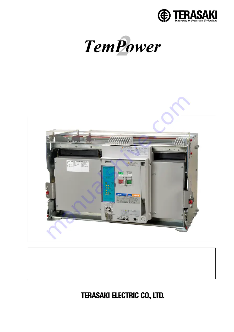
INSTRUCTION MANUAL FOR AIR CIRCUIT BREAKERS


(With Draw-out Cradle and Type AGR-11B Overcurrent Protective Device)


Types: 

AR650S,AR663S,AR663H 


Notice 


Be sure to read this manual before installing, operating, servicing, or inspecting the ACB. 


Please retain this manual for future reference. 


Electrical work must be done by competent persons. 


ACB maintenance, inspection, parts replacement, OCR field tests and setting changes must be 

performed by competent persons.


Summary of Contents for TemPower AR650S

Page 1: ...650S AR663S AR663H Notice Be sure to read this manual before installing operating servicing or inspecting the ACB Please retain this manual for future reference Electrical work must be done by compete...

Page 2: ......

Page 3: ...ing the breaker body back into the draw out cradle 31 4 2 4 Contact status of auxiliary and position switches 33 4 3 ON OFF Button Cover Locking Procedure 33 4 4 Lock in OFF Procedure 34 4 5 Position...

Page 4: ...KRB 5331g 4...

Page 5: ...tions Mounting the ACB in such an area could cause a fire or malfunction Be careful to prevent foreign objects such as debris concrete powder dust chippings and iron powder and oil or rainwater from e...

Page 6: ...hecker optional After completion of OCR tests be sure to return the settings to the original values Failure to do so may cause a fire or burnout Before changing OCR settings open the ACB and then lock...

Page 7: ...the draw out cradle with the fixing bolts When lifting the ACB hold it using lifting attachments or wire ropes through the lifting holes Take care that the control circuit terminals auxiliary switche...

Page 8: ...west possible position Lower the breaker body onto a flat level surface Otherwise the breaker body to fall resulting in damage to the ACB personal injury Take care not to exert forces on the front cov...

Page 9: ...r carry it by the portions 4 points marked with the arrows shown in Fig 3 When carrying the draw out cradle take care not to exert forces on the arc gas barrier the draw out arm the auxiliary switches...

Page 10: ...the draw out operation may cause the breaker body or the draw out cradle to fall resulting in damage to the ACB or personal injury Take care to put the breaker body on a flat level surface Otherwise t...

Page 11: ...le Vertical terminals 48 64 Horizontal terminals 36 48 Use the following screw for the ground terminal The screw must have a length that allows it to be inserted 4 9 mm into the ground terminal M8 tap...

Page 12: ...nals and auxiliary switches 1 Draw out the breaker body to the removed position and remove it using an optional lifter or lifting plate Refer to sections 4 2 2 and 2 1 2 2 If the ACB is equipped with...

Page 13: ...ilted down If any work is done near the ACB that have been installed protect the openings of the ACB with appropriate covers to prevent spatters metal chips wire cuttings or other foreign objects from...

Page 14: ...erminals Control circuit terminal type screw terminals Spring charging method Manual or motor charging Overcurrent release OCR No OCR or L characteristic for general feeder protection Operation indica...

Page 15: ...20V 1 Ambient temperature 40 C 45 C for marine used 2 For 2 pole applications use two poles at both ends 3 4 pole ACBs are not applicable to power distribution IT systems unless N phase protection is...

Page 16: ...te 4kV 100M The above data applies to new ACBs Device terminals within ACBs are not covered Use a DC500V Megger to measure the insulation resistance Table 7 shows the internal resistance and power con...

Page 17: ...Cover fixing screw Overcurrent release OCR 18 OCR cover 17 21 Rating nameplate 9 Position indicator 50 Draw out handle Position padlock lever 13 Release button 12 Draw out handle insertion hole 11 Si...

Page 18: ...arts designation rear view Arc chamber 26 Main circuit contact 24 Mold base 28 25 Control circuit contact 27 Mold cover 23 Breaker body roller 36 Transport roller 10 Grip Gas exhaust port 43 Arc gas b...

Page 19: ...advertently changed Padlocks are not supplied Use padlocks with a 6 mm diameter shackle 18 Overcurrent release OCR This protective device is supplied power via the power CT installed in the ACB main c...

Page 20: ...ircuit terminals 36 and auxiliary switches 39 42 Ground terminal M8 tapped hole Allows connection of a ground terminal 43 Gas exhaust port Allows the arc gas to be discharged from arc chamber 26 in a...

Page 21: ...itch terminals 05 15 Group indication Operation indication contact output terminals 05 17 Trip indication 05 27 Spring charged indication 10 20 AC100V AC110V AC120V AC200V AC220V AC240V DC24V DC48V DC...

Page 22: ...rcuit terminals 02 22 and 03 07 are used for charging and closing operation respectively 9 Do not use these terminals for other circuits when both instantaneously rated shunt trip and UVT are fitted T...

Page 23: ...04 20 26 DC48 36 53 10 1 6 0 51 85 105 DC100 75 110 6 0 8 0 25 350 440 DC110 82 121 6 0 8 0 22 440 540 DC125 93 138 6 0 8 0 21 540 680 DC200 150 220 4 0 5 0 13 1410 1740 DC220 165 242 4 0 5 0 12 1710...

Page 24: ...eder For microload Resistive load A Inductive load A 1 Resistive load A Inductive load A 2 Resistive load A Inductive load A 2 AC100 250 5 5 0 1 0 1 11 6 AC251 500 5 5 DC8 10 6 DC30 1 1 0 1 0 1 6 5 DC...

Page 25: ...ely tightened before using the ACB Loosened fixing bolts may cause a malfunction of the ACB in particular when it is installed in such an area that is subject to strong vibrations The ACBs are availab...

Page 26: ...closed with a sound The ON OFF indicator Fig 15 10 shows ON the charge indicator Fig 15 1 shows DISCHARGED and the charging motor starts charging the closing springs 4 1 3 Opening operation Manual op...

Page 27: ...am 5 rotates counterclockwise so that charging lever 7 disengages from closing spring 6 and rotates counterclockwise Closing cam 8 is pushed up by charging lever 7 and rotates clockwise At this time e...

Page 28: ...ervoltage trip device UVT For tripping operation by the overcurrent release OCR moving core 1 protrudes downward from the magnet hold trigger MHT and trip linkage 2 rotates counterclockwise Parts mark...

Page 29: ...ST position 3 ISOLATED position Insert Draw out In this position the main circuit is isolated and the In this position both the main and control circuits control circuits are connected The ACB can be...

Page 30: ...to push the rail end Do not hold the hook pin body stopper or body stopper shaft Doing so may cause your fingers to be pinched resulting in injury Use the separate draw out handle to draw out the brea...

Page 31: ...2 3 Putting the breaker body back into the draw out cradle DANGER Never touch live terminal parts Otherwise electric shock may result Do not leave the ACB body in the removed position The weight of t...

Page 32: ...out handle insertion hole To close the ACB e g for ON OFF testing remove the draw out handle 4 2 3 3 Moving the breaker body from the TEST position to the CONN position 1 Open the ACB If the ACB rema...

Page 33: ...TEST CONN Status of a contact Status of b contact CONN position indication ON OFF OFF ON TEST position indication ON OFF OFF ON ISOLATED position indication ON OFF OFF ON Inserted position indication...

Page 34: ...er Locking Procedure 1 Move the breaker body to the desired position CONN TEST or ISOLATED 2 Pull out the position lock lever shown in Fig 26 3 Lock the position padlock lever using a padlock with 6 s...

Page 35: ...equired for both the sides of the ACB Fig 27 Securing the breaker fixing bolts 4 7 OCR Cover Locking Procedure Lock the OCR cover using a padlock with 6 shackle as shown in Fig 28 The OCR cover cannot...

Page 36: ...the ACB continuously the root mean square sensing allows the ACB to operate normally The OCR is available in the type that follows AGR 11BL L characteristic for general feeder for works and transform...

Page 37: ...575 775 Max total clearing time ms 120 170 270 470 670 870 8 Short time delay trip I 2 t mode I 2 t tsd ON OFF 9 Instantaneous trip pickup current Ii In 2 4 6 8 10 12 14 16 NON A Tolerance 20 11 Groun...

Page 38: ...Long time delay or N phase protection trip pickup current setting i Overcurrent tR Time setting Note 2 The short time delay trip function has precedence over the long time delay trip function The OCR...

Page 39: ...he right end of the OCR cover to the left at the hollow on the front cover to unlatch and open the OCR cover See Fig 31 If the OCR cover is padlocked first remove the padlock Fig 31 OCR cover 3 Use ro...

Page 40: ...n Type of OCR Control power supply Operation LED Contact output Position State Terminal No See Fig 12 State Normal pickup Trip Alarm Normal Trip Alarm AGR 11BL AL AGR 11BL GL Not required Long time de...

Page 41: ...r Every half year after 2 years since installation Open close condition 800AF or less 1250AF 2500AF 3200AF or more Nearly no current level Every 1000 cycles Every 500 cycles after 1000 cycles Rated cu...

Page 42: ...g an auxiliary do not damage the control wire for the auxiliary or pinch the wire between the auxiliary and the breaker body Doing so may cause a malfunction To ensure safety be sure to perform the pr...

Page 43: ...chips and other damage If dust is accumulated use vacuum cleaner to remove dust and wipe off with dry clean cloth If contact tips are badly discolored or roughened polish with 200 sandpaper 2 If cont...

Page 44: ...on of plunger is 6 3 7 mm when moving core is pushed in If not so replace SHT 14 Hand connector Check that hand connector black is connected to ACB hand connector black correctly If incorrect connect...

Page 45: ...use a malfunction 6 2 1 Preparation Be sure to make the following preparations for parts replacement in order to ensure safety 1 Open an upstream circuit breaker or the like to isolate all sources of...

Page 46: ...lock 4 Turn the UVT mounting screws eight or ten turns to loosen disconnect the manual connector red and then remove the UVT as shown in Fig 37 Fig 37 Removing the UVT Contact block fixing screw Pan h...

Page 47: ...everse order of removal after inspection When installing the UVT make sure the nameplate on the UVT can be viewed from the front of the ACB Fig 39 provides the general view of the UVT Fig 39 General v...

Page 48: ...ed from the arc chamber Fig 40 Arc chamber mounting screws 3 Holding the arc chamber mounting screw remove the arc chamber as shown in Fig 41 Fig 41 Removal procedure of arc chamber 4 Reinstall each p...

Page 49: ...onary arcing contact 1 Make preparations for parts replacement Refer to section 6 2 1 2 Remove the arc chamber Refer to section 6 2 2 3 Unscrew stationary arc contact mounting screws and moving arc co...

Page 50: ...arc contact mounting screw by torque shown in Fig 44 Fig 46 Installation of moving arc contact 6 Reinstall stationary arc contact in reverse order of removal 7 After installing the moving and or stati...

Page 51: ...contact block fixing screws as shown in Fig 35 5 Flip the contact block up as shown in Fig 36 6 Turn the LRC mounting screws eight or ten turns to loosen disconnect the manual connector green and the...

Page 52: ...in Fig 35 5 Flip the contact block up as shown in Fig 36 6 Turn the SHT mounting screws eight or ten turns to loosen disconnect the manual connector black and then remove the SHT See Fig 50 Fig 50 Rem...

Page 53: ...the ACB is equipped with the ON OFF cycle counter disengage the hook located under the cycle counter spring turn the cycle counter fixing screw two or three turns to loosen do not remove and flip the...

Page 54: ...unting screws A and B raise the relay base to unlatch from other parts remove the base and place it on the top of the breaker body To remove relay base mounting screw B use a ball end type 4 mm Allen...

Page 55: ...trol relay from the relay base Fig 56 Control relay and related parts 10 Reinstall each part or component in reverse order of removal after inspection Do not forget to install the OCR ground terminal...

Page 56: ...nector red and remove the MHT Fig 57 Removing the MHT 4 Reinstall each part or component in reverse order of removal after inspection Fig 58 provides the general view of the MHT Fig 58 General view of...

Page 57: ...acement Refer to section 6 2 1 1 and 2 2 If the ACB is equipped with the control terminal block cover loosen both the cover fixing screws and remove the cover 3 Remove the auxiliary switch mounting sc...

Page 58: ...all each part or component in reverse order of removal after inspection When installing the auxiliary switch unit apply molybdenum grease to the engagement of the operation lever and the shaft lever A...

Page 59: ...and 11 in Table 24 OK No NG NG Contact Terasaki OK Check the charging mechanism See No 12 in Table 24 Supply correct voltage Repair NG Repair Is motor charging possible No Contact Terasaki Yes Contac...

Page 60: ...NG NG NG No Is manual closing possible No Charge Move the body to the CONN TEST or ISOLATED position Unlock Deactivate Supply correct voltage Repair replace Repair Contact Terasaki Yes Do operation in...

Page 61: ...able 24 No Check main circuit contacts See No 6 in Table 24 OK No No Yes NG Correct adjust Retighten Repair replace Are OCR settings correct Yes Check the control circuit See No 11 in Table 24 OK Chec...

Page 62: ...0002 Japan TEL 81 6 6791 2763 FAX 81 6 6791 2732 www terasaki co jp kiki info terasaki co jp Published in December 2008 Revised in April 2011 Revised in July 2015 Revised in February 2017 The content...

Reviews: