KRB-5331g
-15-
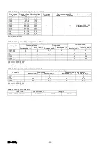
Table 4 High-performance types
Frame size (A)
6300
Type
AR663H
Max. rated current [
I
n
] (A) *1
IEC, EN, AS
6300
Marine use
6300
N-phase rated current (A)
6300
Number of poles *2, *3
3
4
Dielectric withstand voltage [
U
i
] (50/60Hz)
1000
Operating voltage [
U
e
] (50/60Hz)
690
Rated breaking/making current [kA sym rms/kA peak] *4
IEC ,EN, AS [
I
CS
=
I
CU
]
JIS C 8201-2-1 Ann.1 Ann.2
AC 690V *6
85/187
AC 500V
135/297
AC 440V
NK *5
AC 690V
85/201
AC 450V
138/322
For DC
DC 600V *7
40/40
DC 250V
Rated short-time current [
I
CW
] [kA rms]
1 sec.
135
3 sec.
85
Rated latching current (kA)
120
Endurance
in number of
ON-OFF cycles
*8
Mechanical
With maintenance
10000
Without maintenance
5000
Electrical
Without
mainte-n
ance
AC 460V
1000
AC 690V
500
Installation
Draw-out type
Mass (kg) for draw-out type
220
285
External dimensions (mm)
a
799
1034
b
460
c
380
d
60
Connection method
Line side
Vertical terminals
Load side
Vertical terminals
Control circuit terminal type
screw terminals
Spring charging method
Manual or motor charging
Overcurrent release (OCR)
No OCR, or L-characteristic for general feeder protection
Operation indication
Group indication
Tripping device
Tripping coil
(TC)
Standard equipment for OCR-equipped ACB
Shunt trip device
(SHT)
Optional
Undervoltage trip
device (UVT)
Optional
Auxiliary switches
Number of switches
4C (standard), 7C or 10C; available for general feeder or
microload
Terminal type
screw terminals
Operation power*9
Rated voltage
AC100V, AC110V, AC120V, AC200V, AC220V, AC240V,
DC24V, DC48V, DC100V, DC110V, DC125V, DC200V or
DC220V
*1: Ambient temperature: 40
°
C (45
°
C for marine used)
*2: For 2-pole applications, use two poles at both ends.
*3: 4-pole ACBs are not applicable to power distribution IT systems unless N-phase protection is provided.
*4: Setting the instantaneous trip function to NON reduces the rated breaking current to the rated latching current.
*5: Applicable to 3-pole ACBs
*6: For applicability to power distribution IT systems, consult us
*7: Applicable under 3-pole serial connection scheme.
*8: Expected service life based on endurance test. The service life of ACB depends on the working and environmental conditions. Refer to chapter 6
“
Maintenance, Inspection and
Parts Replacement
”
.
*9:
For more information, please refer to page 22.
Use the ACBs in the environmental conditions specified in Table 5.
Table 5 Operating environment
Standard
environment
(Standard equipped
ACBs)
Altitude
2000 m max.
Ambient temperature
-5°C to +40°C The average temperature for 24 hours must not exceed 35°C
Humidity
45 to 85% rel. max.
Vibration
0.7G max.
Shock
200 m/s
2
(20G) max.
Atmosphere
No excessive water vapor, oil vapor, dust, or corrosive gases. No sudden change in temperature and no condensation.
Ammonia (NH
3
): 0.5 ppm max, Hydrogen sulfide (H
2
S)/sulfur dioxide (SO
2
)/hydrogen chloride (HCl): 0.1 ppm max.,
Chlorine (Cl
2
): 0.05 ppm max.
Special
environment
(Optional)
Tropical environment
package
Different from standard ACBs in that Ambient temperature: 60
°
C max. and Humidity: 95% rel. max. (no condensation)
Cold environment
package
Different from standard ACBs in that Ambient temperature: -25
°
C min. for use and -40
°
C min. for storage (no condensation)
Corrosion-resistant
package
Different from standard ACBs in that NH
3
: 50 ppm max, H
2
S: 10 ppm max., SO
2
/HCl: 5 ppm max., and Cl
2
: 1 ppm max.
Summary of Contents for TemPower AR650S
Page 2: ......
Page 4: ...KRB 5331g 4...

