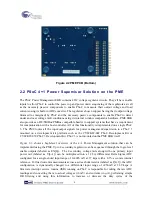
Figure 2-2 PME PCB (Bottom)
2.2
PSoC 4+1 Power Supervisor Solution on the PME
The PSoC Power Management EBK contains 4 DC voltage regulator circuits. They all have enable
inputs to allow PSoC to control the power up and power down sequencing of the regulators as well
as the necessary passive components to enable PSoC to measure their output voltage and load
currents using its built-in ADC converter. The regulators chosen support having their output voltage
trimmed (or margined) by PSoC and the necessary passive components to enable PSoC to detect
under and over voltage fault conditions using its internal window comparator hardware. PME EBK
also provides an I2C/SMBus/PMBus compatible header to support systems that have a requirement
for communication with a host controller. All of this functionality is implemented on a single PSoC
3. The PME routes all the input/output signals for power management/supervision to a PSoC 3
mounted on a development kit platform such as the CY8CKIT-001 PSoC Development Kit or
CY8CKIT-030 PSoC 3 Development Kit. PSoC 3 is not mounted on the PME EBK itself.
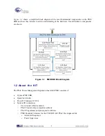
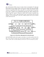
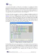
Figure 2-3
shows a high-level overview of the 4+1 Power Management solution that can be
implemented using the PME. Up to 4 secondary regulators can be sequenced through the logic-level
enable outputs (labeled as EN[4]). The 4 secondary voltage rails along with one primary input
power rail (labeled as V[4+1]) can be multiplexed into a 12 bit, differential Delta Sigma ADC
configured for a single-ended input range of 0-4096 mV at 27 ksps with a 0.1% accurate internal
reference. For load current measurements across a series shunt resistor (labeled as I[4+1]), the ADC
configuration is dynamically changed to a differential input range of ±256mV at 22.9 ksps. A
firmware interrupt service routine (ISR) running on PSoC is responsible for taking the raw ADC
readings and converting them to actual voltages (in mV) and currents (in
μ
A), performing simple
IIR filtering and using this information to increase or decrease the duty cycles of the
8
Summary of Contents for CY8CKIT-035
Page 1: ......
Page 38: ...Chapter 5 Schematics 5 1 Primary 12V Power Input 37 ...
Page 39: ...5 2 DVK Connector and Debug Test Points 5 3 Voltage Regulator V1 5V 38 ...
Page 40: ...5 4 Voltage Regulator V2 3 3V 5 5 Voltage Regulator V3 2 5V 5 6 Voltage Regulator V4 1 8V 39 ...
Page 41: ...5 7 I2C SMBus PMBus Interface Connector 5 8 Layout 5 8 1 Top Layer 40 ...
Page 42: ...5 8 2 Ground Layer 5 8 3 Power Layer 41 ...
Page 43: ...5 8 4 Bottom Layer 42 ...
Page 44: ...5 8 5 Top Silkscreen 43 ...


