Application Note P4097
© TeraTron GmbH
Page 18 of 21
V1.1, 07.06.01
external clock (the EC pin is used) and active antenna (data direction of bit#3 must be used) is not
feasible.
The interface to the µController can be a three wire or a two wire connection. The two wire interface
should reduce the number of wires if the P4097 is connected via a wiring harness to the µController.
This configuration is called active antenna. The configuration with the µController on board is called
intelligent antenna.
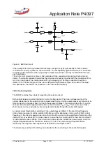
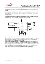
One of the three possible architectures is the direct µController interface. This requires a µController
close to the P4097 which is connected via a three wire interface to the chip.
5V
GND
GND
GND
GND
P4097
1
10
2
3
5
4
6
7
8
9
13
12
11
14
15
16
VSS
CLK
ANT1
DVDD
DVSS
ANT2
VDD
DEMOD_IN
CDEC_OUT
CDEC_IN
CAGND
OUT
IN
CF
CDC
EC
from µC
GND
from µC
to µC
Figure 12.: Direct µController interface
The communication to the chip (writing into the serial shift register) is done synchronously by using the
CLK signal. Diagnosis information is transmitted at the second half of writing into the serial shift
register to the µController by using the CLK signal as well.
Data from the transponder through the chip are transmitted asynchronously, without using the CLK
signal, depending on the used transponder, for example Manchester coded. In this configuration the
EC pin can be left unconnected as it is pulled internally to V
SS
. This configuration uses the PLL for the
antenna clock generation.
The second architecture is the direct µController interface with external clock. The difference is the
usage of a fixed antenna frequency which does not depend on the series resonance.

