Application Note P4097
© TeraTron GmbH
Page 7 of 21
V1.1, 07.06.01
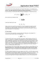
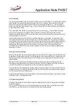
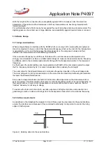
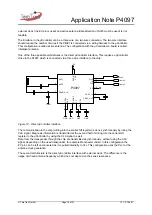
The capacitive voltage divider coming from the antenna tab point to the DEMOD_IN pin should be
dimensioned so that the voltage level never exceeds V
SS
+ 0.5V or V
DD
– 0.5V. Above or below these
thresholds the signal will be clipped and the modulation of this signal is lost. On the other hand the
signal should not be smaller than necessary because the absolute level of modulation should be as
large as possible to achieve a maximum system performance.
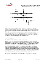
When choosing the values and the tolerance class for this voltage divider (C
in
and C
gnd
in the drawing)
all component tolerances and the variation of antenna quality and resonance frequency over
temperature and part variations should be regarded.
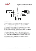
The low pass and high pass filter frequency of the band pass filter following the sampler can be
chosen by the external capacitors connected to CDEC and CDC. They should match with the data
rate and the modulation spectrum of the used transponder. Recommended values are given in the
datasheet.
The low pass filter frequency of the mixer which controls the VCO can be chosen by the external
capacitor connected to CF. The smaller the value is, the faster the settle time is to find the series
resonance of the antenna circuit after starting the antenna driver.
When the capacitance value is selected too small the VCO follows the phase modulation which is
generated by a transponder with a detuned resonance frequency (zero modulation effect). This affects
the phase demodulation and is only recommended if the sample point of the demodulator is always
set on amplitude demodulation (bit#1 set to “0”).
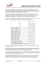
Recommended capacitor values for ASK and ASK/PSK are given in the datasheet.
When the external clock mode is used this capacitor is not needed and the CF pin should be
connected to ground.
The gain of the involved amplifiers can be selected by using bit#6 and bit#7 of the serial shift register.
The influence of different gains should be tested by qualification. In general the sensitivity is increased
with higher gains but the chance of signal clipping and therefore the loss of functionality is also
increased. To easy the gain selection the voltage levels at CEDEC_OUT, CEDEC_IN and CDC can
be monitored. Clipping may occur above V
DD
– 0.5V or below V
SS
+ 0.5V and shall be avoided
considering all tolerances and drifts.
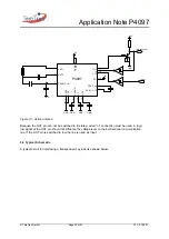
The comparator threshold and its hysteresis can not be modified externally. They are derived from the
internal reference voltage which shall be buffered properly. Voltage ripple on the ground pin of the
connected capacitor relative to the V
SS
pin affects the system performance seriously.
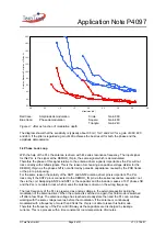
If the internal PLL is used for clock generation the ASK and PSK channel are different in their
sensitivity if a certain bit failure rate is used to determine whether the received signal is valid or not.
The reason for that is the phase jitter of the PLL which generates noise when the phase of the signal
is demodulated. This noise causes a jitter on the pulse length of the digital output.
In general the communication range for the PSK channel is slightly reduced in comparison with the
ASK channel when using the PLL. On the other hand the PSK channel is needed in PLL mode only
when very large tolerances of transponder- and antenna resonance frequencies have to be covered.
When a low jitter external clock is used the performance of the ASK channel and the PSK channel is
the same.
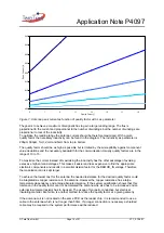
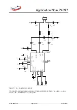
The jitter of the demodulated signal as function of signal strength with the gain as parameter for the
ASK and PSK channel can be seen on the figure below.

