Part No. 40462
DPL-25S • DPL-30S • DPL-35S Super Series
5 - 11
September 2016
Section 5 - Troubleshooting Flow Charts
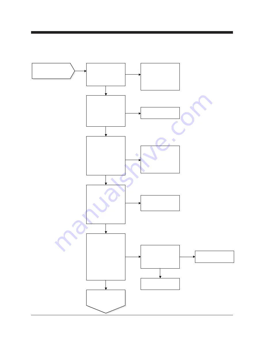
CHART 4
While pushing in and
holding the control
activate switch, check for
power at terminal 4 of the
up switch contact.
Replace the red wire
(because of open circuit)
between the control
activate switch contact
block and the up switch
contact block.
While pushing in the
control activate switch
and activating the up
function, hold both
switches and check for
power at terminal 3 of up
switch contact.
Replace up switch N.O.
contact block.
While pushing in the
control activate switch
and activating the up
function, hold both
switches and check for
power at terminal 13
(orange wire) of 13 pole
terminal strip (J1)in base
control box.
Replace 16/6 cable
because of open in
orange wire OR repair
open in quick disconnect
under ground control box.
Continued from the
previous page.
0V DC
12V DC
0V DC
12V DC
0V DC
While pushing in the
control activate switch
and activating the up
function, hold both
switches and check for
power at terminal 11
(white wire) of 13 pole
terminal strip (J1) in the
ground control box.
0V DC
Replace P.C. board OR
consult Genie Industries
Service Department.
While pushing in the
control activate switch
and activating the up
function, hold both
switches and check for
power at the motor
contactor coil (terminal 1
red wire). Put Neg. lead
of the voltage meter on
terminal 0 green/yellow
wire.
Relocate Neg. lead of the
voltage meter at terminal
10 (green/yellow wire) of
the 13 pole terminal strip
(J1).
Repair open circuit in red
wire.
Repair open circuit in
green/yellow wire.
12V DC
12V DC
12V DC
Continued on the next
page.
0V DC
12V DC
0V DC


