background image

March 2022


Service Manual


Fault Codes 


Part No.    1312899GT


GR

-20J • GR

-26J


91 


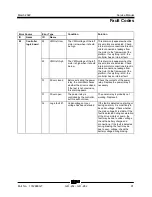
Error Source 

Error Type 

Condition 

Solution 

ID 

Name 

ID 

Name 

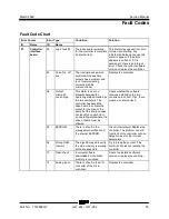
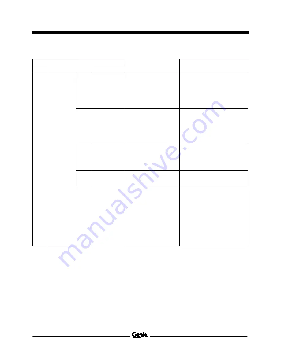
02


Controller 

logic board


28 

VMN left low 

The VMN voltage of the left 

motor is low when it should 

be high. 

This alarm only appears when the 

drive motors are activated. Check: 

internal motor connections. Electric 

cable connections, leakage from 

the motor to the framework of the 

platform. If everything is OK, the 

controller has an internal fault. 

29 

VMN left high 

The VMN voltage of the left 

motor is high when it should 

be low. 

This alarm only appears when the 

drive motors are activated. Check: 

internal motor connections. Electric 

cable connections, leakage from 

the motor to the framework of the 

platform. If everything is OK, the 

controller has an internal fault. 

30 

Driver closed 

Before activating the power 

relay, the controller checks 

whether the driver is closed. 

If the test is not conclusive, 

this alarm appears. 

Check the contacts of the power 

relay. Replace the power relay if 

necessary. 

31 

Driver open 

The power relay is 

controlled by the controller, 

but this will not close. 

The power relay is probably not 

working. Replace it. 

32 

Logic fault #1 

Under-voltage or over- 

voltage has been detected 

If the fault is detected on starting or 

during an alarm, it is most likely to 

be under-voltage. Check whether 

the main voltage SI is stable. If the 

fault is detected during acceleration 

of the drive motors or pump, the 

fault may be due to under- voltage: 

check the battery charge and 

connections. If the fault is detected 

during braking, the fault may be 

due to over- voltage: check the 

battery voltage during braking. 


Summary of Contents for Genie GR-20J

Page 1: ...Service Manual Serial Number Range GR 20J from GRJL 2298 GR 26J Original Instructions Part No 1312899GT Rev A March 2022 ...

Page 2: ...repair be performed at an authorized Genie dealer service center Compliance Machine Classification Group B Type 3 as defined by ISO 16368 Machine Design Life Unrestricted with proper operation inspection and scheduled maintenance Technical Publications Genie has endeavored to deliver the highest degree of accuracy possible However continuous improvement of our products is a Genie policy Therefore ...

Page 3: ...vision Date Section Procedure Page Description A 3 2022 Initial Release Reference Examples Section Maintenance B 3 Electronic Version Click on any content or procedure in the Table of Contents to view the update Section Repair Procedure 4 2 Section Fault Codes All charts Section Schematics Legends and schematics ...

Page 4: ...Service Manual March 2022 Introduction iv GR 20J GR 26J Part No 1312899GT Serial Number Legend 1 Model 2 Facility code 3 Sequence number 4 Serial label 5 Serial number stamped on chassis ...

Page 5: ...n the operator s manual are also safety hazards when maintenance and repair procedures are performed Do not modify or alter a MEWP without prior written permission from the manufacturer Do Not Perform Maintenance Unless You are trained and qualified to perform maintenance on this machine You read understand and obey manufacturer s instructions and safety rules employer s safety rules and worksite ...

Page 6: ...ing hazards such as moving parts free swinging or unsecured components when lifting or placing loads Always wear approved steel toed shoes Workplace Safety Any person working on or around a machine must be aware of all known safety hazards Personal safety and the continued safe operation of the machine should be your top priority Be sure to keep sparks flames and lighted tobacco away from flammabl...

Page 7: ...d iv Section 1 Safety Rules v General Safety Rules v Section 2 Specifications 1 Machine Specifications 1 Performance Specifications 2 Hydraulic Component and Manifold Specifications 3 Manifold Component Specifications 3 Hydraulic Oil Specifications 4 Hydraulic Hose and Fitting Torque Specifications 5 Torque Procedure 6 SAE and Metric Fasteners Torque Charts 8 ...

Page 8: ...els 20 B 4 Test the Drive Brakes 21 B 5 Test the Drive Speed Stowed Position 22 B 6 Test the Drive Speed Raised Position 23 B 7 Test the Flashing Beacon if equipped 24 B 8 Test the Motion Alarm 24 B 9 Visual Inspection of the Hydraulic Oil 25 B 10 Inspect the Breather Cap 26 B 11 Inspect the Rear Axle Free wheel 27 B 12 Inspect the Lateral Offset of the Mast 28 B 13 Inspect the Mast Wear Pads 29 C...

Page 9: ...w to Calibrate the Joystick 38 How to Calibrate the Steer Angle Sensor 39 Platform Components 41 2 1 Platform 41 2 2 Platform Overload System 42 Jib Components 44 3 1 Jib Cylinder 44 Mast Components 46 4 1 Mast Assembly 46 How to Remove the Mast Assembly 46 How to Disassemble the Mast GR 26J 50 How to Assemble the Mast GR 26J 53 How to Disassemble the Mast GR 20J 56 How to Assemble the Mast GR 20J...

Page 10: ...urntable Components 69 9 1 Turntable Rotation Hydraulic Motor 69 9 2 Battery 70 Steer Axle Components 71 10 1 Yoke 71 10 2 Steer Cylinder 71 10 3 Steering Rod 72 10 4 Steer Angle Sensor 73 Non Steer Axle Components 75 11 1 Drive Motors 75 11 2 Drive Brake 77 Battery Charger 78 12 1 Battery Charger 78 Battery Charger Staus Indicator 79 Battery Charger not Operating 79 How to Reset the Battery Charg...

Page 11: ... Switch and Sensor Legend 98 Electrical Symbols Legend 99 Hydraulic Symbols Legend 100 Electrical Schematics 101 Electrical Schematic GRJ from GRJL 2298 102 GCON LED Panel GRJ from GRJL 2298 106 Temperature Sensor Harness GRJ from GRJL 2298 107 Options GRJ from GRJL 2298 110 Hydraulic Schematics 111 Hydraulic Schematic 2 2 kw from GRJL 2298 112 Hydraulic Schematic 3 kw from GRJL 2298 113 ...

Page 12: ...Service Manual March 2022 xii GR 20J GR 26J Part No 1312899GT This page intentionally left blank ...

Page 13: ...00 lbs 227 kg Fluid capacities Hydraulic tank 5 8 gallons 22 liters For operational specifications refer to the Operator s Manual Tires and wheels Tire size solid rubber 16 x 5 x 11 in 40 6 x 12 7 x 28 cm Castle nut torque dry 89 ft lbs 120 Nm Castle nut torque lubricated 66 ft lbs 90 Nm Lug nut torque dry 132 ft lbs 180 Nm Lug nut torque lubricated 96 ft lbs 130 Nm Turntable bearing Rotate bearin...

Page 14: ... h 12 2 m 54 8 sec Braking distance maximum High range on paved surface 60 in 152 cm Gradeability See Operator s Manual Function speed maximum from platform controls with 1 person in platform GR 20J Mast up Mast down 24 26 seconds 19 21 seconds GR 26J Mast up Mast down 54 56 seconds 40 42 seconds GR 20J GR 26J Jib boom up Jib boom down 12 17 seconds 21 26 seconds Turntable rotate 350 32 37 seconds...

Page 15: ...r Lift relief valve pressure 930 psi 64 bar Filter cap torque 37 ft lbs 50 Nm Torque specifications Brake mounting fasteners dry 75 ft lbs 102 Nm Brake mounting fasteners lubricated 56 ft lbs 76 Nm Grease specification RETINAX HDX2 grease NLGI lithium based or equivalent Manif old Co mpo nent Specifica tions Manifold Component Specifications Plug torque SAE No 2 36 in lbs 4 Nm SAE No 4 10 ft lbs 1...

Page 16: ...xaco Hydra 46 Shell Naturelle HF E 46 Note Genie specifications require additional equipment and special installation instructions for the approved optional fluids Consult Genie Product Support before use Optional fluids may not have the same hydraulic lifespan and may result in component damage Note Extended machine operation can cause the hydraulic fluid temperature to increase beyond its maximu...

Page 17: ... 2 6 9 16 18 1 1 2 8 3 4 16 1 1 2 10 7 8 14 1 1 2 12 1 1 16 12 1 1 4 16 1 5 16 12 1 20 1 5 8 12 1 24 1 7 8 12 1 SAE O ring Boss Port tube fitting installed into Aluminum all types SAE Dash Size Torque 4 14 ft lbs 19 Nm 6 23 ft lbs 31 2 Nm 8 36 ft lbs 49 Nm 10 62 ft lbs 84 Nm 12 84 ft lbs 114 Nm 16 125 ft lbs 169 5 Nm 20 151 ft lbs 204 7 Nm 24 184 ft lbs 249 5 Nm Adjustable Fitting Non adjustable f...

Page 18: ...seated and retained properly 4 Position the tube and nut squarely on the face seal end of the fitting and tighten the nut finger tight 5 Tighten the nut or fitting to the appropriate torque Refer to the appropriate torque chart in this section 6 Operate all machine functions and inspect the hose fittings and related components to confirm there are no leaks JIC 37 fittings 1 Align the tube flare he...

Page 19: ...er of flats for the proper tightening position Note The marks indicate the correct tightening positions have been determined Use the second mark on the body hex fitting to properly tighten the joint after it has been loosened Illustration 2 1 body hex fitting 2 reference mark 3 second mark 4 Tighten the hex nut until the mark on the hex nut is aligned with the second mark on the body hex fitting 5...

Page 20: ...Service Manual March 2022 Specifications 8 GR 20J GR 26J Part No 1312899GT SAE and Me tric Fast ene rs Torq ue Ch arts ...

Page 21: ... presented and scheduled may cause death serious injury or substantial damage Immediately tag and remove from service a damaged or malfunctioning machine Repair any machine damage or malfunction before operating the machine Use only Genie approved replacement parts Machines that have been out of service for a period longer than 3 months must complete the quarterly inspection Machine Configuration ...

Page 22: ... a potentially hazardous situation which if not avoided may cause minor or moderate injury Indicates a potentially hazardous situation which if not avoided may result in property damage Indicates that a specific result is expected after performing a series of steps Indicates that an incorrect result has occurred after performing a series of steps Maintenance Symbols Legend Note The following symbo...

Page 23: ...following chart to determine which group s of procedures are required to perform a scheduled inspection Inspection Checklist Daily or every 8 hours A Quarterly or every 250 hours A B Semi annually or every 500 hours A B C Annually or every 1000 hours A B C D Two year or every 2000 hours A B C D E Maintenance Inspection Report The maintenance inspection report contains checklists for each type of s...

Page 24: ... be performed by qualified service technicians according to the manufacturer s specifications and the requirements listed in the responsibilities manual Instructions Use the operator s manual on your machine The Pre delivery Preparation consists of completing the Pre operation Inspection the Maintenance items and the Function Tests Use this form to record the results Place a check in the appropria...

Page 25: ...March 2022 Service Manual Part No 1312899GT GR 20J GR 26J 13 This page intentionally left blank ...

Page 26: ...ompleted Use the step by step procedures in this section to learn how to perform these inspections If any inspection receives an N tag and remove the machine from service repair and re inspect it After repair place a check in the R box Legend Y yes acceptable N no remove from service R repaired Checklist A Y N R Perform after 40 hours A 1 30 day service Perform after 100 hours A 2 Suction strainer...

Page 27: ...dirty or clogged suction strainer may cause the machine to perform poorly and continued use may cause component damage Extremely dirty conditions may require that the suction strainer be replaced more often Bodily injury hazard Beware of hot oil Contact with hot oil may cause severe burns Note When removing a hose assembly or fitting the O ring if equipped on the fitting and or hose end must be re...

Page 28: ...e the drain plug and drain all of the oil into a suitable container 9 Clean up any oil that may have spilled Properly discard the used oil 10 Remove the fasteners securing the function manifold to the hydraulic tank Set the fasteners to the side 11 Loosen the clamp securing the hydraulic power unit to the hydraulic tank Do not remove the clamp 12 Remove the clamp securing the hydraulic power unit ...

Page 29: ...id spilling or contacting battery acid Neutralize battery acid spills with baking soda and water Note Fully charge the batteries and allow the batteries to rest 24 hours before performing this procedure to allow the battery cells to equalize 1 Batteries 2 Fuse 250A 3 Emergency Stop button 4 Motor controller 5 Battery charging indicator 6 Battery charger 1 Open the turntable covers 2 Be sure that t...

Page 30: ...vity reading for each cell as follows Add 0 004 to the reading of each cell for every 10 F 5 5 C above 80 F 26 7 C Subtract 0 004 from the reading of each cell for every 10 F 5 5 C below 80 F 26 7 C Result All battery cells display a specific gravity of 1 277 or greater The battery is fully charged Proceed to step 11 Result One or more battery cells display a specific gravity from 1 218 to 1 269 T...

Page 31: ...sition 3 Raise the jib boom until the platform is approximately 8 feet 2 4 m from the ground 4 Turn the key switch to the off position and push in the red Emergency Stop button to the off position at the ground controls 5 Tag and disconnect the cables from the ground terminal of the battery 6 Remove the fasteners securing the rear chassis cover to the chassis at the non steer end of the machine Re...

Page 32: ...es an d Whe els B 3 Inspect the Tires Wheels and Castle Nut Torque Genie requires that this procedure be performed every 250 hours or quarterly whichever comes first Maintaining the tires and wheels including proper wheel fastener torque is essential to safe operation and good performance Tire and or wheel failure could result in a machine tip over Component damage may also result if problems are ...

Page 33: ... switch to platform control and pull out the red Emergency Stop button to the on position at both the ground and platform controls Note Rotate the red Emergency Stop button at platform control one quarter turn in a clockwise direction to restore the power supply The red Emergency Stop button returns automatically to the out or on position 4 Press the drive function select button 1 drive function s...

Page 34: ... by marking two lines on the ground 40 feet 12 2 m apart 3 Turn the key switch to platform control and pull out the red Emergency Stop button to the on position at both the ground and platform controls Note Rotate the red Emergency Stop button at platform control one quarter turn in a clockwise direction to restore the power supply The red Emergency Stop button returns automatically to the out or ...

Page 35: ... platform control and pull out the red Emergency Stop button to the on position at both the ground and platform controls Note Rotate the red Emergency Stop button at platform control one quarter turn in a clockwise direction to restore the power supply The red Emergency Stop button returns automatically to the out or on position 3 Press the lift function select button 1 lift function select button...

Page 36: ... controls 4 Activate any machine function from the platform control Result The beacons should flash Note The beacon will only flash when you activate any machine function either from ground or platform controls B 8 Test th e M otion Alarm B 8 Test the Motion Alarm Genie specifications require that this procedure be performed every 250 hours or quarterly whichever comes first The motion alarm is us...

Page 37: ...ss and hold the thumb rocker switch for a moment to the right position and then release it Result The alarm should sound B 9 Visual I nspec tion of th e Hyd raulic Oil B 9 Visual Inspection of the Hydraulic Oil Genie specifications require that this procedure be performed every 250 hours or quarterly whichever comes first Replacement or testing of the hydraulic oil is essential for good machine pe...

Page 38: ...istributor until the oil fails the test and is replaced After the oil has been replaced continue the scheduled quarterly maintenance inspection Note When replacing the hydraulic oil it is recommended that all hydraulic filters be replaced at the same time B 10 In spect the B reat her Cap B 10 Inspect the Breather Cap Genie requires that this procedure be performed every 250 hours or quarterly whic...

Page 39: ...te the brake release toggle switch on the top of the ground control box 1 brake release toggle switch 2 ground controls 5 Move the brake release toggle switch to the right to release the brakes Result The parking brakes release and the alarm will sound 6 Remove the wheel chocks and using a fork lift or similar device apply force to the machine Result The machine will move freely Component damage h...

Page 40: ... control and pull out the red Emergency Stop button to the on position at both ground and platform controls Note Rotate the red Emergency Stop button at platform control one quarter turn in a clockwise direction to restore the power supply The red Emergency Stop button returns automatically to the out or on position 2 Raise the jib to the horizontal position 3 Raise the mast head approximately 8 i...

Page 41: ... 200 Kg test weight in the center of the platform Secure the weight to the platform 3 Turn the key switch to ground control and pull out the red Emergency Stop button to the on position at both ground and platform controls Note Rotate the red Emergency Stop button at platform control one quarter turn in a clockwise direction to restore the power supply The red Emergency Stop button returns automat...

Page 42: ...loaded platform condition Machine stability could be compromised resulting in the machine tipping over The platform overload system is designed to detect an overloaded platform and prevent machine operation anytime the machine is turned on When activated the system halts all normal boom operation giving visual and audible warning to the operator Models equipped with the platform overload option ar...

Page 43: ...mes first OR when the machine fails to lift the maximum rated load The hydraulic tank is a vented type tank The breather cap has an internal air filter that can become clogged or over time can deteriorate If the breather cap is faulty or improperly installed impurities can enter the hydraulic system which may cause component damage Extremely dirty conditions may require that the cap be inspected m...

Page 44: ... circuits could result in death or serious injury Remove all rings watches and other jewelry 3 Remove the fasteners securing the chassis side cover next to the tank to the chassis Remove the side cover Lay the side cover and fasteners to the side 4 Place a suitable container under the hydraulic tank Refer to Specifications Machine Specifications 5 Locate and remove the hydraulic tank filler cap Se...

Page 45: ...propriate operator s manual on your machine Be sure that all necessary tools and parts are available and ready for use Use only Genie approved replacement parts Read each procedure completely and adhere to the instructions Attempting shortcuts may produce hazardous conditions Machine Configuration Unless otherwise specified perform each repair procedure with the machine in the following configurat...

Page 46: ...ersonnel to potential personal injury hazards Obey all safety messages that follow this symbol to avoid possible injury or death Indicates a imminently hazardous situation which if not avoided will result in death or serious injury Indicates a potentially hazardous situation which if not avoided could result in death or serious injury Indicates a potentially hazardous situation which if not avoide...

Page 47: ...ing the top plate assembly to the platform control box Carefully remove the top plate assembly from the box to expose the circuit boards 3 Tag and disconnect the wire harness connectors from the platform controls circuit board Electrocution burn hazard Contact with electrically charged circuits could result in death or serious injury Remove all rings watches and other jewelry Component damage haza...

Page 48: ...ons for 3 seconds Result A beep sounds and three function indicator lights will flash one after another 3 Simultaneously press and hold the drive function and the lift function buttons for 3 seconds Result All three function indicator lights will stop flashing 4 Briefly press and release the drive function button to turn the motion alarm on or off Result The drive indicator light will be on if the...

Page 49: ...ds and three function indicator lights will flash one after another 3 Simultaneously press and hold the drive function and the lift function buttons for 3 seconds Result All three function indicator lights will stop flashing 4 Briefly press and release the lift function button to turn the flashing beacon on or off Result The lift indicator light will be on if the flashing beacon is activated It wi...

Page 50: ...will flash one after another 3 Simultaneously press and hold the drive function and jib boom function buttons for 3 seconds Result All three function indicator lights will stop flashing 4 Move the joystick fully to the left then return the joystick to the neutral position Note Do not squeeze or activate the joystick function enable switch No machine function should operate while performing the joy...

Page 51: ...d pull out the red Emergency Stop button to the on position at both the ground and platform controls Note Rotate the red Emergency Stop button at platform control one quarter turn in a clockwise direction to restore the power supply The red Emergency Stop button returns automatically to the out or on position 7 Simultaneously press and hold all three function buttons for 3 seconds Result A beep so...

Page 52: ...second to validate the right side steering limit 13 Press and hold the joystick function enable switch and activate the thumb rocker switch placing the wheels in line with the chassis 14 Press the lift function button for 1 second 15 Press and hold the drive function button for 3 seconds Steer sensor calibration is complete ...

Page 53: ...sembly to the side 6 Remove the fasteners securing the bottom plate assembly to the platform control box Lay the bottom plate assembly and fasteners to the side 7 Remove the fasteners securing the outlet mounting plate to the platform Set the mounting plate assembly and fasteners to the side 8 Attach a lifting strap of suitable capacity from an overhead supporting device to the bottom of the platf...

Page 54: ...e adjusting screws of both the overload sensors Do not over tighten 4 Using a suitable lifting device place an appropriate test weight equal to that of the maximum platform capacity at the center of the platform floor Weight 440 lbs 200 kg 5 Tighten the overload spring adjustment screw just until the screw and lock nut will rotate freely and the clearance between the lock nut and sensor mounting b...

Page 55: ...at the ground and platform controls and the alarm is sounding continuously Proceed to step 10 Result The overload indicator lights are off at the ground and platform controls and the alarm does not sound continuously Repeat the procedure beginning with step 9 10 Test all machine functions from the platform controls Result All platform control functions do not operate 11 Turn the key switch to grou...

Page 56: ...top button at platform control one quarter turn in a clockwise direction to restore the power supply The red Emergency Stop button returns automatically to the out or on position 2 Raise the jib boom to a comfortable working height and place blocks under the platform for support Lower the jib boom until the platform is resting on the blocks 3 Turn the key switch to the off position and push in the...

Page 57: ...der 8 Place a block across both sides of the jib boom under the jib cylinder 9 Use a soft metal drift to remove the barrel end pivot pin and rod end pivot pin 10 Carefully remove the jib cylinder from the machine Crushing hazard The jib boom lift cylinder may become unbalanced and fall when it is removed from the machine if it is not properly supported by the lifting device ...

Page 58: ...ce Procedure Inspect the Mast Wear Pads 2 Using Illustration 1 as a guide create a safety steel plate using the dimensions specified Illustration 1 1 safety steel plate 3 Turn the key switch to the off position and push in the red Emergency Stop button to the off position at both the ground and platform controls 4 Open and remove the turntable covers 5 Remove the fasteners securing the mast head c...

Page 59: ...om and platform assembly could become unbalanced and fall when removed from the machine Component damage hazard Cables and hoses can be damaged if they are kinked or pinched Note During removal the mast head jib boom and platform assembly the overhead crane strap will need to be carefully adjusted for proper balancing A properly balanced lifting strap is essential when removing the assembly from t...

Page 60: ...er to indicate the face closest to the platform with the mark P on the number 1 mast Refer to Illustration 3 17 Remove the mast assembly from the machine while carefully pulling the cables and hydraulic hose from the mast With the P mark facing upwards place the mast assembly on a level workbench capable of supporting it Crushing hazard The mast assembly will fall if it is not properly supported b...

Page 61: ...arch 2022 Service Manual Repair Procedures Part No 1312899GT GR 20J GR 26J 49 GR 26J 1 number 1 mast 2 shims 3 wear pads 4 fasteners 5 stops 6 number 2 mast 7 number 3 mast 8 number 4 mast 9 cover plate ...

Page 62: ... closest to the platform with the P mark on the number 2 3 and 4 mast sections corresponding to the P mark on mast 1 1 number 1 mast 2 number 2 mast 3 number 3 mast 4 number 4 mast 4 Working from the top of the mast assembly push the number 2 3 and 4 mast sections fully into the number 1 mast 5 Remove the fasteners securing the safety steel plate to the mast assembly Set the fasteners and safety s...

Page 63: ...ber 2 mast 13 Remove the fasteners securing stops to the inside of the number 2 mast Remove the stops Set the fasteners and stops to the side 14 Working from the bottom of the number 2 mast pull the number 3 mast half way out 15 Attach a lifting strap from an overhead supporting device to the number 3 mast section Remove the number 3 mast while carefully pulling the it out from the bottom of the n...

Page 64: ...nner wear pads from the top of the number 2 mast section Set the shims to the side Discard the wear pads Note For ease of mast reassembly make careful note of the location order and orientation of the shims Note Use a hammer and chisel if necessary to gently loosen the wear pads from the mast 21 Tag and remove the outer wear pads and shims from the bottom of the number 1 mast section Set the shims...

Page 65: ...isassembly process onto the bottom of mast sections 1 2 3 and 4 1 wear pad 10 mm 2 mast section mast 1 shown 2 Install six 12 mm wear pads and the corresponding shims removed in the mast disassembly process onto the bottom of mast sections 1 2 3 and 4 3 Install two 10 mm wear pads and the corresponding shims removed in the mast disassembly process onto the top of mast sections 1 2 and 3 4 Install ...

Page 66: ... 1312899GT 6 Apply grease onto the outer faces of the mast sections 1 2 3 and 4 7 Carefully assemble the mast sections using the mast disassembly procedure in reverse order Refer to Repair Procedure How to Disassemble the Mast GR 26J 1 grease 2 mast section mast 4 shown ...

Page 67: ...March 2022 Service Manual Repair Procedures Part No 1312899GT GR 20J GR 26J 55 GR 20J 1 number 1 mast 2 stops 3 shims 4 wear pads 5 number 2 mast 6 cover plate ...

Page 68: ...icate the face closest to the platform with the P mark on the number 2 mast section corresponding to the P mark on mast 1 1 number 1 mast 2 number 2 mast 4 Remove the fasteners securing the safety steel plate to the mast assembly Set the fasteners and safety steel plate to the side 5 Remove the fasteners securing stops to the inside of the number 1 mast Set the fasteners and stops to the side 6 Wo...

Page 69: ...gently loosen the wear pads from the mast 10 Tag and remove the inner wear pads and shims from the top of the number 1 mast section Set the shims to the side Discard the wear pads Note For ease of mast reassembly make careful note of the location order and orientation of the shims Note Use a hammer and chisel if necessary to gently loosen the wear pads from the mast How to Asse mble the Mas t GR 2...

Page 70: ...stall six 12 mm wear pads and the corresponding shims removed in the mast disassembly process onto the top mast section 1 5 Apply the grease onto the inner faces of the mast section 1 Grease specification RETINAX HDX2 grease NLGI lithium based or equivalent 1 grease 2 mast section mast 1 shown 6 Apply grease onto the outer faces of the mast sections 1 and 2 1 grease 2 mast section mast 2 shown 7 C...

Page 71: ... Block the non steer tires 2 Open and remove the turntable covers of the machine 3 Center a lifting jack under the drive chassis at the steer end of the machine 4 Raise the steer end of the machine approximately 10 inches 25 cm to access the nut at the bottom of the lift cylinder 5 Place blocks under the chassis for support Lower the machine onto the blocks Crushing hazard The chassis will fall if...

Page 72: ...ifting straps to the platform railings 12 Remove the fasteners securing the mast head to the mast assembly Set the fasteners to the side 13 Raise the mast head jib boom and platform assembly and move the assembly approximately 20 inches 50 cm towards the non steer end of the machine Crushing hazard The mast head jib boom and platform assembly could become unbalanced and fall when removed from the ...

Page 73: ...or assembly remove the fasteners securing the base of level sensor assembly to the chassis 5 Install the new level sensor onto the machine Install and securely tighten the fasteners Do not over tighten 6 Securely install the level sensor pigtail into the machine wire harness 7 Remove the plastic cap from the end of the level sensor calibration wire 8 Using a length of wire approximately 40 inches ...

Page 74: ... the fitting and or hose end must be replaced All connections must be torqued to specification during installation Refer to Specifications Hydraulic Hose and Fitting Torque Specifications Note Perform this procedure on a firm level surface with the machine in the stowed position 1 Disconnect the battery pack from the machine 2 Open and remove the turntable cover at the hydraulic power unit side of...

Page 75: ...p 8 Remove the clamp securing the hydraulic power unit to the chassis Set the clamp to the side 9 Carefully remove the hydraulic power unit from the tank and place it on a clean work bench Note If necessary loosen the bottom connector of auxiliary pump to more easily remove the hydraulic power unit 1 function pump 2 hydraulic tank 10 Remove the fasteners securing the function pump to the function ...

Page 76: ... 4 way B Steer Turntable rotate 18 ft lbs 25 Nm 3 Check valve I Blocks flow from auxiliary pump to function pump 29 ft lbs 40 Nm 4 Solenoid valve 2 position 2 way D Platform up Jib down 18 ft lbs 25 Nm 5 Solenoid valve 2 position 4 way C Turntable rotate left right 18 ft lbs 25 Nm 6 Solenoid valve 2 position 2 way E Platform down Jib down 18 ft lbs 25 Nm 7 Relief valve 930 psi 64 bar G Platform up...

Page 77: ...March 2022 Service Manual Function Manifold Part No 1312899GT GR 20J GR 26J 65 ...

Page 78: ...te Rotate the red Emergency Stop button at platform control one quarter turn in a clockwise direction to restore the power supply The red Emergency Stop button returns automatically to the out or on position 5 From the ground controls fully elevate the jib boom Continue holding jib up while observing the pressure reading on the pressure gauge Note the pressure Refer to Specifications Hydraulic Com...

Page 79: ...form control one quarter turn in a clockwise direction to restore the power supply The red Emergency Stop button returns automatically to the out or on position 5 From the ground controls fully elevate the platform Continue holding platform up while observing the pressure reading on the pressure gauge Note the pressure Refer to Specifications Hydraulic Component Specifications 6 Turn the key switc...

Page 80: ...y injury hazard Spraying hydraulic oil can penetrate and burn skin Loosen hydraulic connections very slowly to allow the oil pressure to dissipate gradually Do not allow oil to squirt or spray 7 Place a suitable container under the hydraulic tank Refer to Section 2 Specifications 8 Locate and remove the hydraulic tank filler cap Set the filler cap to the side 9 Remove the drain plug and drain all ...

Page 81: ...und controls fully elevate the jib boom 3 Turn the key switch to the off position and push in the red Emergency Stop button to the off position at the ground controls 1 turntable rotation motor 2 fasteners 3 hydraulic hoses 4 Remove the rear chassis cover at the non steer end of the machine and set aside 5 Remove the side cover of the drive chassis and set aside 6 Remove the turntable motor cover ...

Page 82: ...e stowed position 1 Turn the key switch to the off position and push in the red Emergency Stop button to the off position at both the ground and platform controls 2 Open and remove the turntable covers 3 Disconnect the battery pack from the machine 4 Locate the bolts between the battery box and the counterweight Loosen the bolts holding the battery pack in position 1 battery box 5 Attach a lifting...

Page 83: ...taining fasteners from the yoke pivot shaft and set aside 12 Remove the yoke assembly from the machine Bodily injury hazard The yoke assembly may fall if not properly supported when it is removed from the machine 10 2 St eer Cylinde r 10 2 Steer Cylinder How to Remove the Steer Cylinder Note When removing a hose assembly or fitting the O ring if equipped on the fitting and or hose end must be repl...

Page 84: ...y hazard Spraying hydraulic oil can penetrate and burn skin Loosen hydraulic connections very slowly to allow the oil pressure to dissipate gradually Do not allow oil to squirt or spray 11 Remove the pin retaining fasteners from the steer cylinder rod end pivot pin Set the washers to the side Discard the cotter pin Note Always replace the cotter pin with a new one 12 Remove the steer cylinder from...

Page 85: ...ed it must be replaced Note the installation and orientation of the old sensor to be sure the new one is installed correctly 6 Remove the steer angle sensor retaining fasteners Remove the steer angle sensor assembly 7 Turn the key switch to platform control and pull out the red Emergency Stop button to the on position at both the ground and platform controls Note Rotate the red Emergency Stop butt...

Page 86: ...re the sensor activator pin is engaged into the sensor 13 Install the plate along with potentiometer on the steer yoke pivot and securely tighten the potentiometer stem with the screw Do not over tighten 14 Install the plastic cap onto the steer yoke pivot 15 Connect the steer angle sensor wire harness to the machine wire harness 16 Calibrate the steer sensor Refer to Repair Procedure How to Calib...

Page 87: ...ate the jib boom 4 Support the jib boom with an overhead supporting device Crushing hazard The jib boom could fall if not properly supported 5 Turn the key switch to the off position and push in the red Emergency Stop button to the off position at the ground controls 6 Open the turntable cover at the ground control side of the machine 1 cable guard 2 right drive motor assembly 3 left drive motor a...

Page 88: ... the machine approximately 6 inches 15 cm Place blocks under the chassis for support 15 Lower the machine onto the blocks Crushing hazard The chassis will fall if not properly supported 16 Remove the castle nut from the wheel at the non steer end of the machine Remove the wheel from the machine Note A properly sized puller may be needed to remove the wheel from the tapered shaft 17 Place a 2 x 4 x...

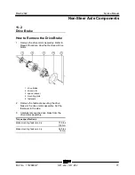
Page 89: ...air Procedure How the Remove a Drive Motor 1 drive brake 2 drive motor 3 speed reducer 4 mounting plate 5 fasteners 2 Remove the fasteners securing the drive brake to the drive motor assembly Set the fasteners to the side 3 Carefully remove the drive brake from the drive motor assembly Torque specifications Brake mounting fasteners dry 75 ft lbs 102 Nm Brake mounting fasteners dry 56 ft lbs 76 Nm ...

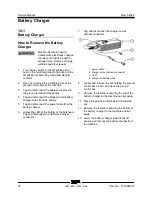
Page 90: ... battery 4 Tag and disconnect the black and red battery charger wires from the battery 5 Tag and disconnect the power cable from the battery charger 6 Locate the LED at the bottom of the bulkhead Tag and disconnect the LED wire harness connector 7 Tag and disconnect the charger cutout harness connector 1 power cable 2 charger cutout harness connector 3 LED 4 charger to battery wires 8 Locate and r...

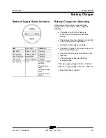
Page 91: ...y C har ger not Ope ratin g Battery Charger not Operating If the battery charger fails to operate when plugged into an AC power source check the following The black wire from the charger is connected to the negative post of the battery The red wire from the charger is connected to the positive post of the battery Corrosion at the battery terminals The battery charger curve selector is set to the c...

Page 92: ...d Emergency Stop button to the off position at both the ground and platform controls 2 Disconnect the battery charger from the AC power source 3 Disconnect the battery charger from the battery 4 Wait 15 minutes 5 Connect the battery charger to the battery 6 Connect the battery charger to an AC power source Result The battery charger operates normally Result The battery charger does not operate Fau...

Page 93: ...ng instructions in the appropriate operator s manual on your machine Be sure that all necessary tools and test equipment are available and ready for use Read each appropriate fault code thoroughly Attempting short cuts may produce hazardous conditions Be aware of the following hazards and follow generally accepted safe workshop practices Crushing hazard When testing or replacing any hydraulic comp...

Page 94: ...ostic readout displays numerical codes that provide the information about the machine operating status and malfunctions 1 Error Source First two digits indicates the affected machine area or component 01 Controller interface board 02 Controller logic board 08 Platform controls circuit board 16 Diagnostic display 2 Third digit always an alphabet A when fault code is displayed 3 Error Type Last two ...

Page 95: ...ating states detected by the two computers The controller has asked the base board to activate the output for the drive or the pump but the interface does not identify a command or an operating state where the drive or pump must be allowed Check whether the software versions installed on the two consoles are correct If so there must be an internal fault 05 EEPROM There is a fault in the management...

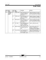
Page 96: ...aking In any other case the fault may be due to an internal fault of the controller then replace it Check whether there is contact or low impedance between pin A12 and the battery Otherwise the circuit is damaged 33 Eb Drv Shorted The electric cable of the brake is in short circuit Check whether there is a short circuit or low impedance between pin A10 and the battery 34 Driver shorted The main co...

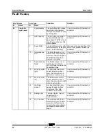
Page 97: ... Check the condition of the overload sensors or change the controller 55 Overcharge Overload fault Check the condition of the overload sensors or change the controller 56 Battery low Low battery voltage If the alarm is triggered when the battery is fully charged change the controller 57 No CAN signal The interface board has not received the CAN signal Check the BUSCAN connection between the module...

Page 98: ...nt The battery parameter differs by more than 20 from the nominal battery voltage Check the battery type parameter 64 Charge in progress The platform has been started up with the battery charger in operation If the alarm appears with the charger disconnected from the mains there may be a problem with the connection of terminal A17 Otherwise it is an internal fault of the controller 65 Value of ang...

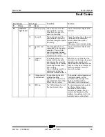
Page 99: ... the controller 83 Steering valve There is a problem on one or other of the following outputs terminal A34 terminal A26 Check the condition of the valves and their connections Otherwise it is an internal fault of the controller 84 Aux Valve There is a problem on one or other of the following outputs FLASHING LIGHT and TILT LAMP Repair or replace the option 86 Brake coil open The main driver coil i...

Page 100: ...al fault Replace the controller 11 Thermal sensor faulty The thermal sensor is not functioning correctly its output voltage is outside the acceptable range It is an internal fault Replace the controller 12 Stand by motor right The right armature current sensor detects a current other than zero when the right motor is not running It is an internal fault Replace the controller 13 Stand by motor left...

Page 101: ...ernal charge is in parallel with the capacitor and reduces the current of the recharge circuit thereby preventing the capacitors from charging There is a problem with the charging circuit and the controller must be replaced When the key is connected the controller tries to charge the power capacitors via a resistor and checks whether the capacitors are charged If they do not charge an alarm is gen...

Page 102: ...internal fault 25 Pump VMN high The VMN voltage of the pump is high when it should be low This alarm appears while the pump is working Check internal pump connections Electric cable connections leakage from the pump to the framework of the platform If everything is OK the controller has an internal fault 26 VMN right low The VMN voltage of the right motor is low when it should be high This alarm o...

Page 103: ...k of the platform If everything is OK the controller has an internal fault 30 Driver closed Before activating the power relay the controller checks whether the driver is closed If the test is not conclusive this alarm appears Check the contacts of the power relay Replace the power relay if necessary 31 Driver open The power relay is controlled by the controller but this will not close The power re...

Page 104: ...ump If the controller board detects a problem in its own control circuit this alarm appears It is an internal fault Replace the controller 44 Driver1 The interface and logic board performs a counter check of signals for the steering choice If the logic detects a problem in its own control circuit field conductor circuit this alarm appears It is an internal fault Replace the controller 46 No ground...

Page 105: ...ng with the signal 60 High temperatures The power section of the fuse has reached the temperature limit the maximum current is automatically reduced The alarm disappears as soon as the cutout cools down If this does not happen there is a problem with the internal temperature sensor 65 Value of angle sensor incorrect The value read by the potentiometer is different from the programmed value Check t...

Page 106: ...o ground or to positive on output CNE 5 Check the wiring If the wiring is correct and the alarm persists there is an internal fault 74 SV3 4 incorrect There is a problem short circuit to negative or to positive on output CNE 1 or CNE 3 Check the wiring If the wiring is correct and the alarm persists there is an internal fault 75 BUSCAN incorrect The platform controls circuit board is not receiving...

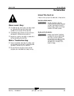
Page 107: ...the safety rules and operating instructions in the appropriate operator s manual on your machine Be sure that all necessary tools and test equipment are available and ready for use About This Section There are two groups of schematics in this section Electrical Schematics Electrocution burn hazard Contact with electrically charged circuits could result in death or serious injury Remove all rings w...

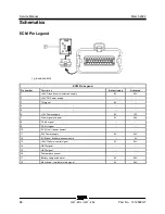
Page 108: ...ion supply 0V 24V 2 24V DC Power supply 3 Tilt signal 0V 4 5 6 12V Power supply 0V 12V 7 Steer signal mid point 0V 2 5V 8 CAN L signal 9 CAN H signal 10 0V AU coil power contact 11 24V Power supply 0V 24V 12 0V Brake Brake release solenoid 0V 13 24V Platform control signal 0V 24V 14 HBT3 signal 15 HBT2 signal 16 Temperature sensor 17 Battery charger indicator 0V 24V 18 Mast down turntable rotate s...

Page 109: ... 24V 21 Jib signal 0V 24V 22 Turntable rotate signal 0V 24V 23 24V Solenoid valve F2 fuse power 0V 24V 24 0V Tilt indicator LED 24V 0V 25 0V Turntable rotate valve 24V 0V 26 0V Mast base valve 24V 0V 27 28 0V Steer valve 24V 0V 29 0V Horn 24V 0V 30 0V Mast down valve 24V 0V 31 Overload indicator LED 24V 0V 32 0V Mast up valve 24V 0V 33 34 0V Power supply selection valve 24V 0V 35 0V Flashing beaco...

Page 110: ...2022 Limit Switch and Sensor Legend 98 GR 20J GR 26J Part No 1312899GT Limit Switch and S enso r Le gen d Limit and Sensor Legend 1 Platform overload LS31 2 Mast down LS18 3 Steer angle S21 4 Tilt sensor S7 5 Jib down LS11 ...

Page 111: ...its Crossing no connection Switch or Button Motor Level Sensor Diode Toggle Switch Battery Charger Solenoid Valve Connection no terminal Emergency Stop Button Battery Parking Brake Connector Key Switch Control Relay Electric Motor Fuse Horn or Alarm Joystick Controller Flashing Beacon LED Sensor hydraulic oil temperature ...

Page 112: ... acting Filter Relief valve with pressure setting Motor bi directional Solenoid operated 2 position 2 way directional valve Solenoid operated 2 position 2 way directional valve Solenoid operated 2 position 2 way directional valve Solenoid operated 2 position 4 way directional valve Hose reel Solenoid operated 2 position 2 way directional valve Solenoid operated 2 position 4 way directional valve ...

Page 113: ...March 2022 Service Manual 101 Electrica l Schemati cs Electrical Schematic GRJ from GRJL 2298 ...

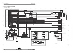
Page 114: ... 1 2 1 2 1 2 211 245 1 2 3 4 5 6 7 8 X10³ SENSORS TEMPERATURE EV TO4 TEMP SENSOR EV HARNESS 211 281 240 241 242 243 244 1 2 3 4 5 6 1 2 1 2 3 4 5 6 AC105 FLASHING LIGHTS TO 4 INTERFACES AC104 STEERING SENSOR BRAKES TO 4 CHASSIS HARNESS AC120 MDI AC113 TRACKUNIT EASYMANAGER TO 4 OPTIONS X106 ANTI START TO 4 OPTIONS 1 2 3 4 5 6 7 8 9 10 11 12 1 2 3 4 5 6 7 8 9 10 11 12 13 14 211 263 209 151 3 148 14...

Page 115: ...327 326 353 356 355 366 365 354 319 363 341 342 343 345 346 347 348 351 350 352 3 398 1 2 3 4 5 6 7 8 9 10 11 12 X301 1 2 3 4 5 6 7 8 9 10 11 12 13 14 1 2 3 4 5 6 7 8 9 10 11 12 13 14 X3J1 J1 1 2 3 4 1 2 3 4 X3J3 J3 325 372 361 375 374 373 377 376 364 362 328 327 326 325 324 360 363 324 1 2 3 4 5 6 1 2 3 4 5 6 J2 J2 PLATFORM LED PANEL 361 364 360 362 363 324 324 324 324 324 PLATFORM MEMBRANE KEYPA...

Page 116: ...Service Manual March 2022 104 Electrical Schematic GRJ from GRJL 2298 ...

Page 117: ...March 2022 Service Manual 105 GCON LED Panel GRJ from GRJL 2298 ...

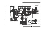
Page 118: ...5 6 7 8 9 10 11 12 262 261 226 228 230 229 210 211 227 203 223 322 J2 211 211 F2 F1 322 223 1 2 3 4 1 2 3 4 1 2 3 4 5 6 1 2 3 4 5 6 J3 J3 223 230 229 228 227 226 223 223 223 223 B o N RIGHT ROTATION LIFTING LEFT ROTATION LOWERING JIB SELECTOR TURNTABLE SELECTOR TELESCOPE SELECTOR J1 J1 TILT LED OVERLOAD LED GROUND PLATFORM KEY SWITCH ES0630 A ...

Page 119: ...1 281 211 244 211 243 211 240 211 242 211 241 211 281 211 244 EV5 EV5 EV8 EV8 EV6 EV6 EV7 EV7 DS104 DS104 EV4 EV4 211 243 211 240 211 242 211 241 211 281 211 244 1 2 1 2 1 2 1 2 1 2 1 2 1 2 1 2 1 2 1 2 1 2 1 2 STEERING COIL JIB LOWERING COIL TURNTABLE ROTATION COIL LIFT COIL TEMPERATURE SENSOR POWER SUPPLY COIL TS100 AC104 AC111 AC105 EV10 207 3 253 266 149 399 3 211 263 211 245 Vcc out Ref 0v 1 2...

Page 120: ...Service Manual March 2022 108 Temperature Sensor Harness GRJ from GRJL 2298 ...

Page 121: ...March 2022 Service Manual 109 Options GRJ from GRJL 2298 ...

Page 122: ...ckunit info 7 Ground 9 Input2 10 output2 14 APC 24v SMS option 323 322 399 363 3 323 322 399 363 3 1 2 3 4 5 6 7 8 9 10 11 12 13 14 15 1 2 3 4 5 6 7 8 9 10 11 12 13 14 15 1 2 3 4 1 2 3 4 1 2 3 4 1 2 3 4 1 2 1 2 1 2 399 3 399 3 322 YL GR white white white VJR SMS HARNESS BLUE FLASHING LIGHT HARNESS AC111 AC111 pink purple pink gray RESET PUSHBUTTON A01 APC R1200 SENSITIVE EDGE to joystick Power Sup...

Page 123: ...March 2022 Service Manual 111 Hydraulic Sc hema tics Hydraulic Schematic 2 2 kw from GRJL 2298 ...

Page 124: ...c 2 2 kw from GRJL 2298 T1 M Only GR 26J 2030 psi 140 bar H 1450 PSI 100 bar A B Y116 Y117 Y118 928 psi 64 bar Y22 Y21 EV10 EV11 EV12 TP 0 66 gpm 2 5 L min P2 P3 P1 P1 P6 T2 P4 2 2 KW 0 26 cu in 4 2 cm 3 1 22 cu in 20 cm 3 HS0284 A B I D C E G A F STEER 1450 PSI 100 bar TURNTABLE ROTATE REEL MAST UP DOWN JIB UP DOWN AUX PUMP ...

Page 125: ...3 kw from GRJL 2298 T1 M Y116 Y117 Y118 Y22 Y21 EV10 EV11 EV12 TP P2 P3 P1 P1 P6 T2 P4 3 KW A B 2030 psi 140 bar 1450 psi 100 bar 0 26 cu in 4 2 cm 3 0 26 cu in 4 2 cm 3 1 22 cu in 20 cm 3 HS0284 A H I F AUX PUMP B D C E G A 928 psi 64 bar 1450 psi 100 bar 0 66 gpm 2 5 L min STEER TURNTABLE ROTATE REEL MAST UP DOWN JIB UP DOWN ...

Page 126: ...Service Manual March 2022 114 Hydraulic Schematic 3 kw from GRJL 2298 GR 20 J GR 2 6J Part No 131 289 9GT Service Manu al Marc h 20 22 ...

Page 127: ......
Reviews: