Service Manual
March 2022
Mast Components
46
GR
™
-20J • GR
™
-26J
Part No. 1312899GT
Mast Components
4-1 Mast Ass embly
4-1
Mast Assembly
How to Re mov e th e M ast Asse mbly
How to Remove the Mast
Assembly
Note: When removing a hose assembly or fitting,
the O-ring (if equipped) on the fitting and/or hose
end must be replaced. All connections must be
torqued to specification during installation. Refer to
Specifications,
Hydraulic Hose and Fitting Torque
Specifications.
Bodily injury hazard. This
procedure requires specific repair
skills, lifting equipment and a
suitable workshop. Attempting
this procedure without these
skills and tools could result in
death or serious injury and
significant component damage.
Dealer service is strongly
recommended.
Note: Perform this procedure on a firm, level
surface with the machine in the stowed position.
1 Check the condition of the wear pads. Refer
to Maintenance Procedure,
Inspect the Mast
Wear Pads.
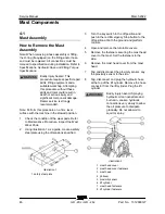
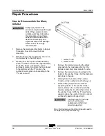
2 Using Illustration 1 as a guide, create a safety
steel plate using the dimensions specified.
Illustration 1
1 safety steel plate
3 Turn the key switch to the off position and
push in the red Emergency Stop button to the
off position at both the ground and platform
controls.
4 Open and remove the turntable covers.
5 Remove the fasteners securing the mast head
cover to the mast. Set the fasteners to the
side.
6 Remove the mast head cover from the mast
head.
7 Tag and disconnect the proximity sensor. Lay
the proximity sensor to the side.
8 Tag, disconnect and plug the hydraulic hose
at the top of the lift cylinder. Remove the hose
connector from the lift cylinder. Plug the lift
cylinder.
Bodily injury hazard. Spraying
hydraulic oil can penetrate and
burn skin. Loosen hydraulic
connections very slowly to allow
the oil pressure to dissipate
gradually. Do not allow oil to
squirt or spray.
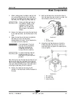
Illustration 2
1 mast head cover
2 mast head cover fasteners
3 mast head
4 jib boom
5 proximity sensor
6 lift cylinder
7 mast head fasteners
8 lift cylinder fasteners
Summary of Contents for Genie GR-20J
Page 77: ...March 2022 Service Manual Function Manifold Part No 1312899GT GR 20J GR 26J 65 ...
Page 113: ...March 2022 Service Manual 101 Electrica l Schemati cs Electrical Schematic GRJ from GRJL 2298 ...
Page 116: ...Service Manual March 2022 104 Electrical Schematic GRJ from GRJL 2298 ...
Page 117: ...March 2022 Service Manual 105 GCON LED Panel GRJ from GRJL 2298 ...
Page 120: ...Service Manual March 2022 108 Temperature Sensor Harness GRJ from GRJL 2298 ...
Page 121: ...March 2022 Service Manual 109 Options GRJ from GRJL 2298 ...
Page 127: ......


