Service and Repair Manual
March 2021
Manifolds
64
GS
™
-30 • 32 • 46 • 47
Part No. 1272217GT
5-8
Valve Adjustments - Function
Manifold
Note: Perform this test from the ground with the
platform controls. Do not stand in the platform.
Note: Verify the hydraulic oil level is at the FULL
mark on the hydraulic tank.
How to Adjust the System Relief
Valve
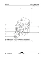
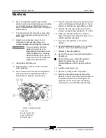
1 Locate the system relief valve on the function
manifold (schematic item I, AB or DB).
2 Connect a 0 to 5000 psi / 0 to 350 bar
pressure gauge to the test port on the function
manifold. (schematic item A, AA or DA).
3 Chock both sides of the wheels at the steer
end of the machine.
4 Remove the platform controls from the
platform.
5 Turn the key switch to platform controls and
pull out the red Emergency Stop button to the
on position at both ground and platform
controls.
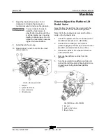
GS-1530/32 and GS-1930/32
1 test port
2 system relief valve
6 Move and hold the joystick fully in either
direction while observing the pressure reading
on the pressure gauge. Note the pressure.
Refer to Specifications,
Hydraulic Component
Specifications.
7 Turn the machine off. Hold the system relief
valve with a wrench and remove the cap. I,
AB or DB).

