May 2015
Service Manual
Non-steer Axle Components
Part No. 1257106
GS-2669 BE • GS-3369 BE • GS-4069 BE
111
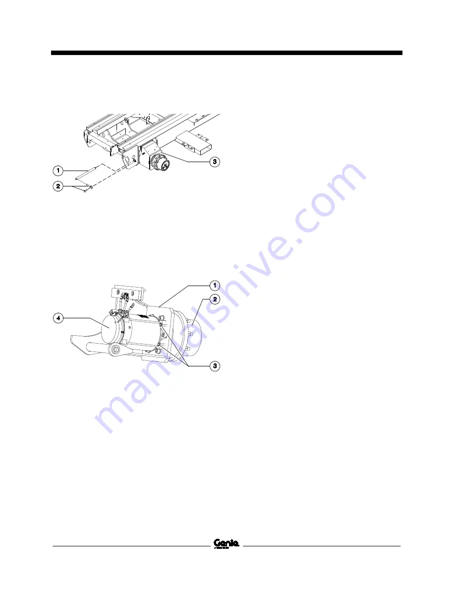
11 Using a suitable supporting device, secure the
rear axle assembly. Do not apply pressure.
1 axle pivot pin
2 retaining fasteners
3 axle assembly
12 Remove the axle pivot pin retaining fasteners.
13 Using a soft metal drift, remove the axle pivot
pin. Remove the axle assembly from the
machine.
1 axle assembly
2 drive hub
3 retaining fasteners (x4)
4 drive motor
14 Remove the retaining fasteners that secure
the drive motor to the drive hub.
15 Support and slide the drive motor shaft out of
the drive hub. Remove the drive motor from
the machine.
Summary of Contents for Genie GS-2669 BE
Page 1: ...Service Manual GS 2669 BE GS 3369 BE GS 4069 BE Part No 1257106 Rev A3 May 2015...
Page 27: ...May 2015 Service Manual Specifications Part No 1257106 GS 2669 BE GS 3369 BE GS 4069 BE 11...
Page 100: ...Service Manual May 2015 Manifolds 84 GS 2669 BE GS 3369 BE GS 4069 BE Part No 1257106...
Page 173: ...May 2015 Service Manual 157 Contactor Box Layout All Models...
Page 176: ...Service Manual May 2015 160 Ground Control Box Layout All Models...
Page 177: ...May 2015 Service Manual 161 Platform Control Box Layout All Models...
Page 180: ...Service Manual May 2015 164 Generator Wiring Diagram All Models...
Page 185: ...May 2015 Service Manual 169 Electrical Schematic GS 4069 BE with 2 Speed Lift ANSI CSA...
Page 188: ...Service Manual May 2015 172 Electrical Schematic GS 4069 BE with Proportional Lift ANSI CSA...
Page 193: ...May 2015 Service Manual 177 Electrical Schematic GS 4069 BE with 2 Speed Lift AS CE...
Page 196: ...Service Manual May 2015 180 Electrical Schematic GS 4069 BE with Proportional Lift AS CE...
Page 197: ...May 2015 Service Manual 181 Hydraulic Schematic GS 2669 BE and GS 3369 BE with 2 Speed Lift...
Page 201: ...May 2015 Service Manual 185 Hydraulic Schematic GS 4069 BE with 2 Speed Lift...
Page 205: ......


