Service Manual
May 2015
Outrigger Components
114
GS-2669 BE • GS-3369 BE • GS-4069 BE
Part No. 1257106
11-2
Outrigger Calibration
The Electronic Control Module (ECM) is
programmed to deactivate the drive and steer
functions while the outriggers are deployed and
activate an alarm when a signal is received from
the outrigger level sensor, indicating the outriggers
are not deployed or the machine is out of level.
The ECM is also used to calibrate the outrigger
level sensor to achieve a levelness of 0° +/- 0.5°
front to back and side to side, while the outriggers
are deployed.
For further information or assistance, consult the
Genie Product Support.
How to C alibr ate the Outri gger System
How to Calibrate the Outrigger
System
Move the machine to an area that has a firm, level
surface and is free of obstructions.
1 Turn the key switch to the ground controls
position and pull out the red Emergency Stop
button to the on position at the platform
controls.
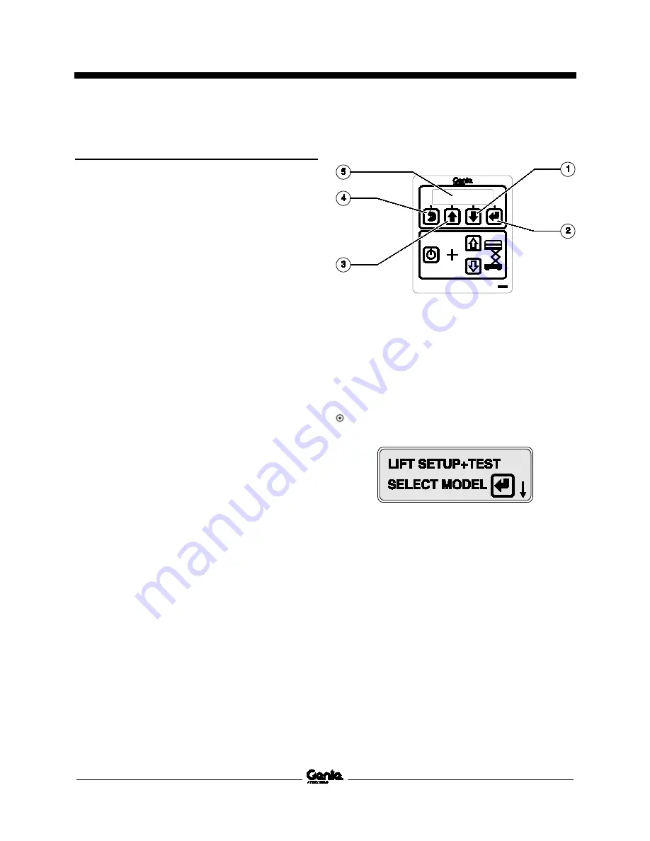
2 Press and hold the ground control scroll up
and scroll down buttons.
1 scroll down button
2 enter button
3 scroll up button
4 escape button
5 LCD display
3 Pull out the red Emergency Stop button to the
on position at the ground controls.
Result: The ground controls LCD display will
show the following:
4 Release the Scroll Up and Scroll Down
buttons after the ground controller powers up.
5 Use the Scroll Up or Scroll Down buttons to
scroll to Machine Options.
6 Press the Enter button to select Machine
Options.
Summary of Contents for Genie GS-2669 BE
Page 1: ...Service Manual GS 2669 BE GS 3369 BE GS 4069 BE Part No 1257106 Rev A3 May 2015...
Page 27: ...May 2015 Service Manual Specifications Part No 1257106 GS 2669 BE GS 3369 BE GS 4069 BE 11...
Page 100: ...Service Manual May 2015 Manifolds 84 GS 2669 BE GS 3369 BE GS 4069 BE Part No 1257106...
Page 173: ...May 2015 Service Manual 157 Contactor Box Layout All Models...
Page 176: ...Service Manual May 2015 160 Ground Control Box Layout All Models...
Page 177: ...May 2015 Service Manual 161 Platform Control Box Layout All Models...
Page 180: ...Service Manual May 2015 164 Generator Wiring Diagram All Models...
Page 185: ...May 2015 Service Manual 169 Electrical Schematic GS 4069 BE with 2 Speed Lift ANSI CSA...
Page 188: ...Service Manual May 2015 172 Electrical Schematic GS 4069 BE with Proportional Lift ANSI CSA...
Page 193: ...May 2015 Service Manual 177 Electrical Schematic GS 4069 BE with 2 Speed Lift AS CE...
Page 196: ...Service Manual May 2015 180 Electrical Schematic GS 4069 BE with Proportional Lift AS CE...
Page 197: ...May 2015 Service Manual 181 Hydraulic Schematic GS 2669 BE and GS 3369 BE with 2 Speed Lift...
Page 201: ...May 2015 Service Manual 185 Hydraulic Schematic GS 4069 BE with 2 Speed Lift...
Page 205: ......


