background image

Third Edition • Sixth Printing


Operator's Manual


 Operating 

Instructions 


Part No. 237108


GTH-844 35 


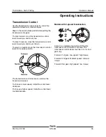
Transmission Control 

Use the transmission control lever to control the 
speed and direction of machine travel. 

Step on the service brake pedal before putting the 
transmission into gear. 

To drive forward, move the transmission control 
lever toward you and move it up. 

To drive in reverse, move the transmission control 
lever toward you and move it down. 

To return to neutral, move the transmission control 
lever to the center position. 


The transmission control lever also controls the 
transmission speed. 

To choose a lower speed, rotate the control lever 
clockwise. 

To choose a higher speed, rotate the control lever 
counterclockwise. 


Models with 3-speed transmission 


Come to a complete stop before shifting the 
transmission from forward to reverse. The 
transmission control lever must be in 1st or 2nd 
gear only. 

Forward / 1st gear: Low speed / high torque 

Forward / 2nd gear: Medium speed / medium 
torque 

Forward / 3rd gear: High speed / low torque 

Summary of Contents for Genie GTH-844

Page 1: ...Operator s Manual GTH 844 with Maintenance Information Third Edition Sixth Printing Part No 237108...

Page 2: ...18 Inspections 22 Operating Instructions 33 Transport and Lifting Instructions 44 Maintenance 47 Attachments 51 Specifications 63 Load Charts 64 Copyright 2012 by Terex Corporation Third Edition Sixt...

Page 3: ...icking transporting and placing loads with the established load range charts Use of this product in any other way is prohibited and contrary to its intended use Bulletin Distribution and Compliance Sa...

Page 4: ...your machine Please register your machine by visiting us on the web at www genielift com or by calling us toll free at 1 800 536 1800 Danger Failure to obey the instructions and safety rules in this...

Page 5: ...ath or serious injury Indicates a hazardous situation which if not avoided could result in minor or moderate injury Indicates a property damage message Standards Many aspects of rough terrain forklift...

Page 6: ...GTH 844 Part No 237108 Safety Sign Maintenance Replace any missing or damaged safety signs Keep operator safety in mind at all times Use mild soap and water to clean safety signs Do not use solvent ba...

Page 7: ...tion hazard Use a piece of cardboard or paper to search for leaks Maintain required clearance Crush hazard Always wear seat belt Tip over hazard Tip over hazard Crush hazard Keep away from moving part...

Page 8: ...xth Printing Symbol and Hazard Pictorials Definitions 6 GTH 844 Part No 237108 Explosion Burn hazard No smoking No open flame Keep load low Fall hazard Only use an approved work platform Refer to load...

Page 9: ...art No 237108 GTH 844 7 General Safety 214418 237599 214419 82558 237598 237598 237605 215268 237601 97602 97667 214418 28175 237971 237598 237970 214418 237970 214418 214419 237599 215268 237970 2375...

Page 10: ...ral Safety 8 GTH 844 Part No 237108 82560 237720 237720 215644 237726 215648 237722 133031 215646 82473 215645 237720 215644 215646 215646 237721 215647 215646 215647 237721 215648 215644 237720 82560...

Page 11: ...nd the telehandler being in good operating condition If using accessories read understand and obey the decals instructions and manuals with the accessory Do not raise the load unless the ground can su...

Page 12: ...hen the machine is loaded always travel with the load uphill When the machine is unloaded travel with the forks or attachment downhill On steep terrain drive only up and down a hill and always keep th...

Page 13: ...ar an elevated boom whether it is loaded or unloaded Do not put the transmission into gear unless the brake is applied and personnel and bystanders are clear of the machine and load Do not drive the m...

Page 14: ...rn skin Relieve pressure before disconnecting hydraulic lines Keep away from leaks and pin holes Use a piece of cardboard or paper to search for leaks Do not use your hand Fluid injected into skin mus...

Page 15: ...nuals are complete legible and in the storage container located in the cab Do not attempt to start the machine by towing or pushing Do not attempt to use the forks or attachments for prying wedged or...

Page 16: ...tion and make sure personnel and bystanders are kept clear of moving parts during operation Burn Hazards Allow hot surfaces to cool before touching or servicing Explosion and Fire Hazards Do not start...

Page 17: ...over 1000kV see below For power lines over 1000kV the minimum clearance distance must be established by the utility owner or operator or by a registered professional engineer who is a qualified perso...

Page 18: ...spilling or contacting battery acid Neutralize battery acid spills with baking soda and water Explosion Hazards Keep sparks flames and lighted tobacco away from batteries Batteries emit explosive gas...

Page 19: ...ng wheel 4 Control handle 5 Front to rear level indicator 6 Boom angle indicator 7 Boom 8 Cab 9 Hydraulic oil level gauge under cover 10 Engine on opposite side of machine 11 Fuse panel 12 Forks 13 Ex...

Page 20: ...switch 7 Parking brake switch 8 Ignition switch 9 Load charts 10 Control handle 11 Auxiliary hydraulics switch if equipped 12 Accelerator pedal 13 Brake pedal 14 Tilt steering pedal 15 Axle differenti...

Page 21: ...brake off The light will be off when the parking brake is off 8 Ignition switch Turn the key to the left to turn on the accessories Turn the key to the on position and hold until the glow plug light o...

Page 22: ...turn the wiper off 17 Skylight washer wiper switch if equipped Push the right side of the rocker switch to turn the wiper on Push and hold the right side of the rocker switch to turn the washer on Re...

Page 23: ...indicator light 11 Engine oil pressure low indicator light 12 Check engine indicator light 13 Engine stop indicator light 14 Four wheel steer indicator light 15 Two wheel steer indicator light 16 Crab...

Page 24: ...s designed to discover if anything is apparently wrong with a machine before the operator performs the function tests The pre operation inspection also serves to determine if routine maintenance proce...

Page 25: ...ection Check the following components or areas for damage improperly installed or missing parts and unauthorized modifications Electrical components wiring and electrical cables Hydraulic hoses fittin...

Page 26: ...he machine as it was intended Function Test Fundamentals The function tests are designed to discover any malfunctions before the machine is put into service The operator must follow the step by step i...

Page 27: ...boom Result All functions should operate smoothly 9 Using the control handle and the red thumb switch momentarily tilt the forks up and tilt the forks down Result All functions should operate smoothl...

Page 28: ...s should not turn 19 Straighten the wheels 20 Push the left side of the steer selector switch to select crab steer The crab steer indicator light on the instrument panel will be on 21 Check the steeri...

Page 29: ...ator light is off 32 Put the transmission control lever in forward Slowly let up on the brake pedal Result The drive function should not operate 33 Put the transmission control lever in neutral 34 Pus...

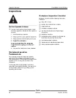
Page 30: ...r determine if the workplace is suitable for safe machine operation It should be performed by the operator prior to moving the machine to the workplace It is the operator s responsibility to read and...

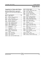
Page 31: ...azard Work Platform 1 215384 Label FOPS ROPS 1 215652 Label Dual Controller 1 216208 Label LED Chart 1 219648 Label Load Chart Rotate Carriage 1 Part No Decal Description Qty 219703 Cosmetic Genie GTH...

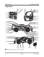
Page 32: ...m view i e under covers 114090 237600 114115 load chart set 214418 237599 215384 237606 215652 133206 214419 82558 237598 237598 237605 236083 215268 237601 97602 97667 214418 28175 Serial Label 23608...

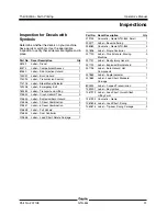
Page 33: ...plosion Burn Hazard 1 215646 Label 2 Decal Combination 3 215647 Label 6 Decal Combination 1 215648 Label Fall Hazard 1 215652 Label Dual Controller 1 219648 Label Load Chart Rotate Carriage 1 Part No...

Page 34: ...is hidden from view i e under covers 160482 114090 114115 load chart set 215646 237721 237606 215652 133206 215647 82560 237720 237720 215644 237726 236083 215648 237722 133031 215646 82473 Serial Lab...

Page 35: ...les and instructions in the operator s safety and responsibilities manuals A variable reach rough terrain forklift truck is defined as a wheeled type truck designated primarily as a fork truck with a...

Page 36: ...p the machine Push and release the brake pedal to control the machine speed Starting the Engine 1 Be sure the parking brake is set and the transmission control lever is in the neutral position 2 Inser...

Page 37: ...lever toward you and move it down To return to neutral move the transmission control lever to the center position The transmission control lever also controls the transmission speed To choose a lower...

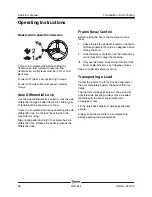
Page 38: ...le differential lock Release the pedal to release the differential lock Frame Sway Control Before raising the boom the machine must be level 1 Check the left to right level indicator The left to right...

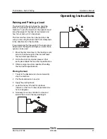
Page 39: ...load cannot be placed at the height and angle you want these options can be used 1 Move the machine closer to the loading or pick point so that the weight of the load will meet the load chart specifi...

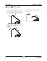
Page 40: ...extend the boom into final position Lower the load until the weight is completely off the forks Do not apply a downward force with the forks 7 Gradually move the controller to raise and retract the b...

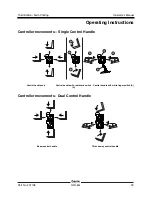
Page 41: ...ions Part No 237108 GTH 844 39 Controller movements Single Control Handle Control handle only Control handle with red thumb switch A Control handle with white finger switch B Controller movements Dual...

Page 42: ...ck If the boom is raised above 55 the transmission will shift to neutral and the frame sway function will not operate Boom and fork functions continue to operate To unlock the rear axle and to operate...

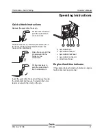
Page 43: ...attachment Raise the boom until the pin is secured in the hooks on the attachment Tilt the forks back to pivot the quick attach into the attachment Insert the quick attach lock pin all the way through...

Page 44: ...ld result from the machine moving forward or backward To avoid personal injury when jump starting with another machine be certain that the machines are not touching Never jump start a frozen battery a...

Page 45: ...ne unless the mast and equipment are in their proper travel position Whether a machine will tip over during dynamic machine operation involves many variables that need to be considered Among these are...

Page 46: ...r with expertise in preparing loading and securing construction and lifting equipment for international shipment Only qualified operators should move the machine on or off the truck The transport vehi...

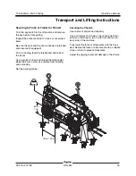
Page 47: ...ading level the telehandler and retract the boom Use a spotter to load and unload the telehandler Keep the boom as low as possible when loading and unloading Set the parking brake Securing the Chassis...

Page 48: ...he crane capacity loading surfaces and straps or lines are sufficient to withstand the machine weight See the serial label for the machine weight Lifting Instructions Fully lower and retract the boom...

Page 49: ...ing of a maintenance procedure it conveys the meaning below Indicates that tools will be required to perform this procedure Indicates that new parts will be required to perform this procedure Indicate...

Page 50: ...ulfur Diesel LSD Deutz TCD 3 6 L4 Tier 4i Engine Fuel Type Ultra Low Sulfur Diesel ULSD Check the Hydraulic Oil Level Maintaining the hydraulic oil at the proper level is essential to machine operatio...

Page 51: ...al protectors and a corrosion preventative sealant will help eliminate the corrosion on the battery terminals and cables Check the Engine Coolant Level Liquid Cooled Models Maintaining the engine cool...

Page 52: ...d tire can explode and may cause death or serious injury Note This procedure does not need to be performed on machines equipped with foam filled tires 1 Check each tire with an air pressure gauge Add...

Page 53: ...ructed regarding the specific hazards associated with using the telehandler with the work platform and utilize all means including those provided by the user or employer to avoid them Always perform a...

Page 54: ...the platform Do not climb down from the platform when raised Do not place or attach overhanging loads to any part of this machine or platform Do not place ladders or scaffolds in the platform or agai...

Page 55: ...at operators of other overhead and floor level machines are aware of the machine s presence Lifting Personnel Occupants equipment and materials shall not exceed the maximum platform capacity Distribut...

Page 56: ...cted by the occupants Always lift and lower personnel smoothly and with caution and only at their request Operating Instructions Preparation and Setup Read understand and obey all jobsite local state...

Page 57: ...try point gate or railing before signaling to be lifted Attach PFPE to the designated lanyard anchor Occupants should use the guardrail to help stabilize themselves during movement Be aware of crushin...

Page 58: ...d be used to support a suspended load The telehandler load charts are designed for loads where the load center is stationary As a suspended load moves the load center can change As a result extreme ca...

Page 59: ...r a swinging load or to adjust the load after it has been raised Do not try to move fixed or obstructed loads Do not leave the telehandler unattended with a suspended load Keep the boom and load as lo...

Page 60: ...Do not suspend loads using slings or chains from the forks or fork carriage Avoid lifting double tiered loads Lifting a Suspended Load Verify that landing point is level and can safely support the lo...

Page 61: ...he telehandler to a complete stop Start stop travel and turn slowly to prevent the load from becoming unstable or swinging Do not travel faster than walking speed 2 mph 3 2 km h Placing the Load Ask a...

Page 62: ...aveling the view in the direction of travel is obstructed Due to site specific safety concerns either the operator or the person handling the load determines that it is necessary Signal persons must r...

Page 63: ...fingers closed RAISE THE BOOM AND LOWER THE LOAD With arm extended horizontally to the side and thumb pointing up fingers open and close while load movement is desired DOG EVERYTHING Hands held togeth...

Page 64: ...connection of a load to a component or structure and are within the fall zone all of the following criteria must be met The materials being hoisted must be rigged to prevent unintentional displacemen...

Page 65: ...2000 lbs 907 kg Maximum lift capacity 8000 lbs 3629 kg Drive speed maximum Deutz engines 3 speed transmission 15 mph 24 1 km h 2 speed transmission 6 mph 10 5 km h Drive speed maximum Perkins 854 engi...

Page 66: ...844 Part No 237108 Operator s Manual Third Edition Sixth Printing 10 ft 3 0 m 30 ft 9 1 m 35 ft 10 7 m 0 ft 0 m 5 ft 1 5 m 10 ft 3 0 m 30 ft 9 1 m 40 ft 12 2 m 20 ft 6 1 m 1600 lbs 726 kg 0 ft 0 m 0...

Page 67: ...tributed By www genielift com California Proposition 65 Warning The exhaust from this product contains chemicals known to the State of California to cause cancer birth defects or other reproductive ha...

Reviews: