May 2015
66 GTH 4016 R - GTH 4018 R - GTH-5021 R Part No. 57.0009.0607
Second Edition - First Printing
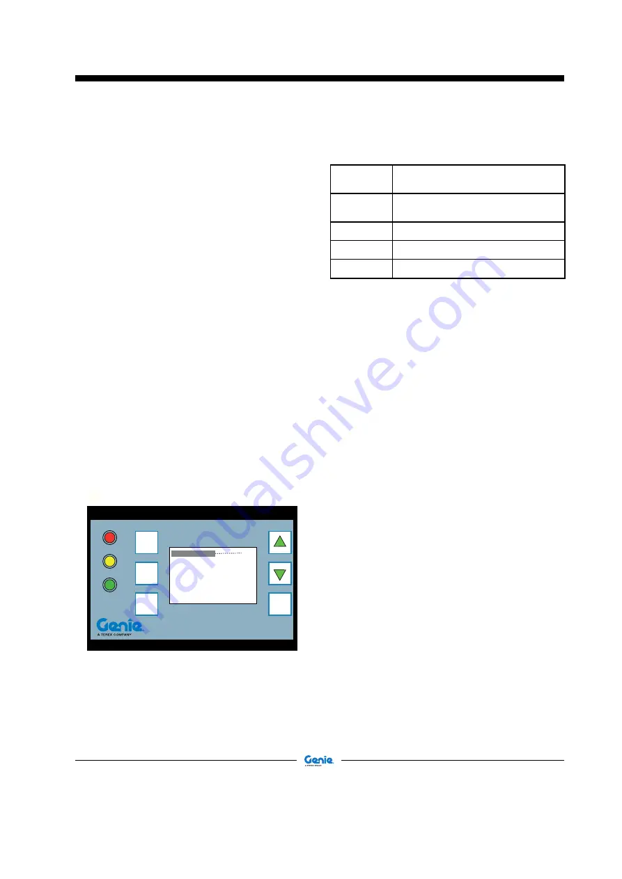
Load Limiting System control
panel
At the back of the driving place there is a unit which
lets you manage the load limiting system of the
machine.
The collected data, processed in relation to the
attachment used, are continuously compared with the
data stored in the program memory. The processing
of these data results in three different situations
which are displayed by the warning lights located
at the left side of the display.
1
Green LED ON
Stability condition. The raised load does not
exceed 90% of maximum allowed load of the
chart in that defined working position.
2
Yellow LED ON
Pre-alarm condition. The raised load exceeds
90% of maximum allowed load, but it is still
inferior to it: the boom movements are slowed
down and the acoustic alarm slowly beeps.
3
Red LED ON
Alarm condition. The raised load exceeds the
maximum allowed load, the acoustic alarm
quickly beeps and the machine motions are
stopped, but for those allowing to return the load
within safety limits.
ENTER
FORKS
OUTRIGGERS LATERAL
MAX LOAD ........................ 50.3t
RAISED LOAD ................... 10.2t
HEIGHT............................... 2 m
RADIUS............................... 7 m
ANGLE................................ 15°
55%
ESC
+
-
The display is divided into three areas:
LED’s area:
Three LED’s warn of the variation of
the working condition:
1
green LED
- machine stable
2
yellow LED
- machine in pre-alarm
3
red LED
- machine in alarm
Control Keys
ESC
To go back to the previous screen
page
ENTER
To confirm and open the screen
page linked
ARROWS
To scroll the lines up or down
PLUS (
+
)
Additional selection button
MINUS (
-
)
Additional selection button
Display, which is divided into 8 lines_ fig.A
1.
Load percentage strip
2.
Indicates the attachment used
3.
Indicates the operating mode
4.
Indicates the max load that can be raised
5.
Indicates the weight raised for the system
calibration
6.
Indicates the boom height (it’ll be
= 0 meters
once the boom is fully lowered)
7.
Indicates the distance of the load from the
slewing axis and, in case of necessity, it
displays the related warning message
8.
Indicates the boom angle
When using an attachment other than those stated,
but supplied by Terex Global GmbH, select the
FORK in line 2.
Operation
•
At the machine starting, the load limiting system
runs an automatic check and the software data
are displayed.
•
Within 3/4 seconds, the list of attachments
allowed is displayed: using the arrows, the
operator has to select the right attachment and
then press
ENTER
to confirm.
•
Once the attachment has been selected, the
display shows the
Standard Screen Page
(
fig.A
).
•
From this screen page, pushing
PLUS
(
+
)
for some seconds, the operator can open the
UPPER LEVEL (B)
where other four sub-menus
are displayed: one of these,
LANGUAGE
can
be modified while the other three,
CLOCK
,
EXTENSION SENSOR
and
ANGLE SENSOR
,
can only be consulted.
Operating Instructions
A


