background image

April 2019

First Edition - Fourth Printing

Part No. 

57.0009.0729

                             GTH-4014 AU, GTH-4018 AU 

35 

Inspections                                                          

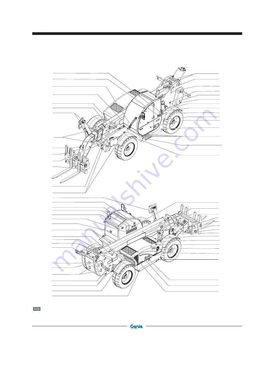
Shading indicates decal is hidden from view, i.e. under covers

237720

215644

215648

09.4618.1375

215646

09.4616.0040

215646

09.4618.0242

215645

28159

09.4618.1686

09.4618.1685

{

09.4618.1681

09.4618.1423

237721

09.4618.1506

09.4618.1616

{

09.4618.1681

09.4618.1398

09.4618.0933

09.4618.1683

09.4618.1739

{

09.4618.1645

09.4618.1458

09.4618.0933

09.4618.0243

237720

215644

237726

09.4618.1423

09.4618.1674

09.4618.1418

09.4618.1679

09.4618.0920

09.4618.0924

09.4618.0923

09.4618.1689

AUS1000

09.4618.1687

09.4618.0916

09.4618.1678

09.4618.1670

09.4618.0933

09.4618.1506

09.4618.1616

{

09.4618.1507

09.4618.1617

{

09.4618.1681

215646

09.4618.1713

09.4618.1681

09.4618.0923

09.4618.1399

AUS1529

09.4618.0916

52475

AUS1529

 09.4618.0916

52475

09.4618.1386

09.4618.1773

AUS1529

09.4618.0916

52475

52475

09.4618.0922

AUS1529

09.4618.1848

09.4618.1419

09.4618.1399

Summary of Contents for Genie GTH4018 SR

Page 1: ...Operator s Manual Original Instructions First Edition Fourth Printing Part No 57 0009 0729 Serial number range GTH 4014 AU From serial n GTH401415B 101 GTH 4018 AU From serial n GTH401815B 101 ...

Page 2: ... 66 Attachments 75 Specifications 86 Load Charts 87 Copyright 2019 by Terex Corporation First Edition Fourth Printing April 2019 Genie is a registered trademark of Terex South Dakota Inc in the U S A and many other countries GTH is a trademark of Terex South Dakota Inc April 2019 First Edition Fourth Printing II GTH 4014 AU GTH 4018 AU Part No 57 0009 0729 Terex Australia Pty Ltd 33 Kimberley St D...

Page 3: ...idered a permanent part of your machine and should remain with the machine atalltimes Ifyouhaveanyquestions contactGenie Product Identification The machine serial number is located on the serial label Serial number stamp Serial label if present Homologation plate if present Intended Use A variable reach rough terrain forklift truck is defined as a wheeled type truck with pivoting boom which maybee...

Page 4: ...you receive important safety maintenance and operating information that applies to your machine Please register your machine by visiting us on the web at www genieindustries com au Introduction Bulletin Distribution and Compliance Safety of product users is of paramount importance to Genie Various bulletins are used by Genie to communicate important safety and product information to dealers and ma...

Page 5: ...understand the safety rules before going on to the next section 2 Always perform a pre operation inspection 3 Always perform function tests prior to use 4 Inspect the workplace 5 Only use the machine as it was intended Youread understandandobeythemanufacturer s instructions and the safety rules the safety and operator s manuals and the decals applied on the machine You read understand and obey the...

Page 6: ... which ifnotavoided couldresult in death or serious injury CAUTION Indicates a hazardous situation which ifnotavoided couldresult in minor or moderate injury NOTICE Indicates a property damage message Introduction Standards The following standards and or regulations apply to this machine Directive AS 1418 19 2007 cranes hoists and winches Part 19 Telescopic handlers Safety Sign Maintenance Replace...

Page 7: ...nd manual Tip over hazard Always wear seat belt Keep load low during travel Crush hazard Crush hazard Crush hazard Keep away from moving parts Burn hazard Do not loosen cap until cool Keep away from moving parts No smoking No open flame Tip over hazard Symbol and Hazard Pictorials Definitions Explosion hazard Do not use starting aids No people under load Apply maintenance collar Crush hazard Explo...

Page 8: ... 09 4618 0920 215646 237726 09 4618 0922 09 4618 0922 09 4618 0923 09 4618 0923 09 4618 1674 237726 215644 237720 09 4618 0922 09 4618 0923 09 4618 0924 09 4618 0924 09 4618 1458 09 4618 1458 09 4618 0924 09 4618 1458 09 4618 0923 09 4618 0920 09 4618 1713 09 4618 1713 09 4618 1713 09 4618 1423 215646 237720 09 4618 1423 09 4618 1423 215644 ...

Page 9: ...4618 1423 215645 09 4618 1375 09 4618 1375 215648 237721 237720 215646 09 4618 1423 215644 09 4618 1375 215648 215646 09 4618 0933 237721 215646 09 4618 1679 09 4618 1683 for GTH 4018 09 4618 1739 for GTH 4014 09 4618 0933 237720 215645 215644 09 4618 0933 09 4618 0933 09 4618 1683 P max 6 4 kg cm 2 09 4618 1683 09 4618 1739 P max 4 6 kg cm 2 09 4618 1739 ...

Page 10: ...achine level indicator should be at zero degrees Do not level the machine using the frame levelling control unless the boom angle indicator is at zero degrees or less Do not work with the load limiting system cut out Do not use the levelling control to position an elevated load Do not raise a load and then drive to position it When driving keep the boom at or below horizontal and keep the load clo...

Page 11: ... under the outriggers of the machine Type of ground soil characteristics Allowable superficial pressure KPa2 loose non compact soil generally speaking not solid special precautions needed loamy peaty pasty soil rippable soft ground non cohesive well com pact soil sand gravel 200 rippable soil solid 100 semi solid 200 hard 400 Rocks concrete heavy traffic paved roads above 1000 Table 1 Make sure th...

Page 12: ...y loaded and on transfer mode boom fully lowered and retracted max inclination driving downhill 9 max inclination driving uphill 20 max lateral inclination 6 On steep terrain drive only up and down a hill and always keep the machine in gear Do not turn across the slope when the machine is traveling up or down a slope Limit travel path and speed according to the condition of the ground surface trac...

Page 13: ...s equipped keep the volume low enough to hear surrounding environment i e traffic alarms people etc Donotadjustthecontrolswhiledrivingormanoeuvring a load Scan the area prior to operating the machine Look in the direction of travel Use mirrors and the camera to assist in checking all around the machine Keep windows and mirrors clean adjusted and in good repair Be aware of the machine load swing ar...

Page 14: ...ct with components under any cover will cause serious injury Only trained maintenance personnel should access compartments Access by the operator is only advised when performing a pre operation inspection All compartments must remain closed and secured during operation Damaged Machine Hazards Do not use a damaged or malfunctioning machine Conduct a thorough pre operation inspection of the machine ...

Page 15: ...he machine Keep clear of elevated components Supportcomponentsbeforeperformingservice Keep clear of moving parts during machine operation Burn Hazards Allow hot surfaces to cool before touching or servicing Explosion and Fire Hazards Do not start the engine if you smell or detect liquid petroleum gas LPG gasoline diesel fuel or other explosive substances Do not refuel the machine with the engine r...

Page 16: ... 72 m over 1000kV see below For power lines over 1000kV the minimum clearance distance must be established by the utility owner or operator or by a registered professional engineer who is a qualified person with respect to electrical power transmission and distribution Do not use the machine as a ground for welding Always contact the electrical power line owner The electrical power shall be discon...

Page 17: ...emit explosive gas Work Area Safety Electrocution Hazard Avoid contact with electrical terminal Using the Charger if equipped be sure the device works at 12 Volt and doesn t exceed 15 Ampere During maintenance or repair works and while welding disconnect the battery by turning the cut out switch see Inspection for Decals section Employer s Responsibilities Employers are responsible for providing a...

Page 18: ...s and diagrams the identification and hazard warning plates They shall be skilled and trained about the machine use The operator shall have a licence or a driving licence when provided for by the laws enforced in the country where the machine is operated Please ask the competent bodies Requirements for service personnel Personnel in charge of machine maintenance shall be qualified specialised in t...

Page 19: ...ny other comfortable garments Operators should not wear clothes with large sleeves or objects that can get stuck in moving parts of the machine Protective helmet Protective gloves Working shoes Use only approved safety workwear in good condition Personal protective equipment Under special working conditions the following personal protective equipment should be used Breathing set or dust mask Ear p...

Page 20: ... intended for warning of the risk of overturning in the case of a sudden overload travelling with the load in the elevated position travelling on rough terrain or on grounds with obstacles and holes travelling across a slope or turning on a slope driving in bends too fast or too sharp Adjustments affecting the setting of the Load Management System shall be performed only by authorised personnel Se...

Page 21: ...ft rear view mirror 4 Rear fish eye mirror 5 Boom angle indicator 6 Maintenance collar on opposite side of machine 7 Fuel filler 8 Hydraulic oil level gauge on opposite side of machine 9 Engine on opposite side of machine 10 Forks 11 Seat belt 12 Outriggers 13 Front rear level indicator 14 Right rear view mirrors 15 Rear Camera if equipped 13 8 4 11 6 1 14 9 5 2 3 10 7 12 15 ...

Page 22: ...April 2019 20 GTH 4014 AU GTH 4018 AU Part No 57 0009 0729 First Edition Fourth Printing Controls P ERROR 12 6 28 19 18 8 5 15 16 21 24 25 31 23 4 26 13 27 9 7 14 11 29 20 22 1 17 30 10 3 2 ...

Page 23: ...nd air conditioning controls 13 Instrument panel display toggle button 14 Accelerator pedal 15 Brake pedal 16 Ignition switch 17 DPF switch EU model 18 Steering column tilt adjustment lock 19 Job site road platform selector 20 Hydraulic quick coupling enabling switch if equipped 21 Cab heater fan switch 22 Auxiliary hydraulic circuit switch if equipped 23 Mixing bucket switch if equipped 24 A C sw...

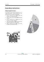
Page 24: ... Rotatethesteerselectortotherightsidetoselect four wheel steer Rotate the steer selector to the middle position to select two wheel steer Rotate the steer selector to the left to select crab steer 6 Load Management System override key switch See Load Management System section 7 Load Management System control panel See Load Management System section 8 Emergency stop push button See Control Indicato...

Page 25: ...the top of the switch to turn the A C off 25 Hazard warning lights switch if equipped Push the bottom of the switch to turn the hazard warning lights on Push the top of the switch to turn the hazard warning lights off 26 Emergency pump switch if equipped Pushtheswitchtoactivatetheemergencypump Releasetheswitchtostoptheemergencypump 27 Gear selection switch Push the bottom of the rocker switch to t...

Page 26: ...dicator light only EU version 9 High exhaust system temperature indicator light only EU version 10 Engine air filter restricted indicator light 11 Alert indicator light 12 Engine Critical Fault indicator light 13 2nd gear engaged indicator light 14 1st gear engaged indicator light 15 Engine coolant temperature gauge with high coolant temperature indicator light 16 Position light indicator light 17...

Page 27: ... light indicates that a regeneration has been inhibited 9 High exhaust system temperature indicator light When illuminated this light indicates that a regeneration is underway and that emission system temperatures are elevated 10 Engine air filter restricted indicator light When this lamp comes on the engine air filter is clogged proceed with cleaning or changing the air filter cartridge 11 DPF Al...

Page 28: ...e inspection is designed to discover if anything is apparentlywrongwithamachinebeforetheoperator performs the function tests Thepre operationinspectionalsoservestodetermine ifroutinemaintenanceproceduresarerequired Only routine maintenance items specified in this manual may be performed by the operator Refer to the list on the next page and check each of the items If damage or any unauthorized var...

Page 29: ...ons Electrical components wiring and electrical cables Hydraulic hoses fittings cylinders and manifolds Fuel and hydraulic tanks Drive motors and drive hubs Boom wear pads Tires and wheels Mirrors Camera system Engine and related components Limit switches Lights alarms and beacons Pins nuts bolts and other fasteners LMS front and rear cameras if equipped and their cables Check entire machine for C...

Page 30: ...ce 5 Only use the machine as it was intended Function Test Fundamentals The function tests are designed to discover any malfunctions before the machine is put into service Theoperatormustfollowthestep by stepinstructions to test all machine functions A malfunctioning machine must never be used If malfunctions are discovered the machine must be tagged and removed from service Repairs to the machine...

Page 31: ...forks up and down Result All functions should operate smoothly 9 Using the roller switch momentarily extend and retract the boom Result All functions should operate smoothly Test the Hydraulic Quick Coupling Lock Unlock if equipped 10 While pressing the dedicated switch push and hold the white thumb button and use the control handle momentarily lock unlock the hydraulic quick coupling Result All f...

Page 32: ...edal to increase the RPM s and slowly let up on the brake pedal As soon as the machine starts to move push the brake pedal Result The machine should move in reverse and then come to an abrupt stop The reversing alarm should sound when the transmission control lever is in reverse 23 Move the transmission control lever to neutral 24 Push the bottom of the parking brake switch Result The red parking ...

Page 33: ...d road lights are functional Test the Load Management System 37 Load a known weight of approximately 1000 kg 38 Raise the boom about 30 cm above the ground Inspections 39 Extend the boom and check if the system enters the alarm mode once it has reached the distance as indicated in the load charts for the attachment fitted to the machine Result the system alarm mode should sound and boom movement s...

Page 34: ...amera view when the boom movement is complete Test the Emergency Pump if equipped 49 Set the ignition switch to position I 50 Press the emergency stop push button 51 Press the Emergency Pump switch for some seconds 52 Engage any of the manual levers while pressing the Emergency Pump switch Result the corresponding movement of the machine will indicate the Emergency Pump is working properly Test th...

Page 35: ...ion helps the operator determineiftheworkplaceissuitableforsafemachine operation Itshouldbeperformedbytheoperatorprior to moving the machine to the workplace Itistheoperator sresponsibilitytoreadandremember theworkplacehazards thenwatchforandavoidthem while moving setting up and operating the machine Workplace Inspection Checklist Be aware of and avoid the following hazardous situations drop offs ...

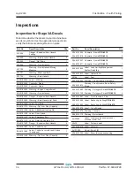
Page 36: ...ncy Exit 1 09 4618 1419 Label Naturelle Hydraulic Oil 1 09 4618 1423 Danger Explosion Burn Hazard 4 09 4618 1687 Label Control Lever 1 09 4618 1689 Label Control Lever with Lock Unlock if equipped 1 09 4618 1458 Warning Tip Over Obey Capacity 2 Part No Decal Description Qty 09 4618 1506 09 4618 1616 Cosmetic Genie GTH 4018 Cosmetic Genie GTH 4014 2 2 09 4618 1507 09 4618 1617 Cosmetic Genie GTH 40...

Page 37: ... 09 4618 1683 09 4618 1739 09 4618 1645 09 4618 1458 09 4618 0933 09 4618 0243 237720 215644 237726 09 4618 1423 09 4618 1674 09 4618 1418 09 4618 1679 09 4618 0920 09 4618 0924 09 4618 0923 09 4618 1689 AUS1000 09 4618 1687 09 4618 0916 09 4618 1678 09 4618 1670 09 4618 0933 09 4618 1506 09 4618 1616 09 4618 1507 09 4618 1617 09 4618 1681 215646 09 4618 1713 09 4618 1681 09 4618 0923 09 4618 1399...

Page 38: ...nuals A variable reach rough terrain forklift truck is defined as a wheeled type truck designated primarily as a fork truck with a pivoted telescopic boom which may be equipped with attachments for lifting material Using it for any other purpose is unsafe and dangerous Only trained and authorized personnel should be permitted to operate a machine If more than one operator is expected to use a mach...

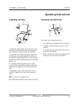
Page 39: ...e green zone To adjust the backrest operate lever D press your back firmly against the backrest and put the backrest at the angle you wish then release the lever To adjust the armrest raise armrest E and turn wheel F to adjust the armrest at the height you want The seat is for one person only Don t adjust the seat when the machine is moving Fastening the Seat Belts 3 2 1 Sit correctly in the drivi...

Page 40: ...otate them to the position s which provides optimal visibility 1 Allows checking the area behind the machine on the right hand side 2 Allows checking the carriageway behind the machine 3 Allows checking the area behind the machine on the left hand side 4 Allows checking the area behind the machine as well as the rear part of the chassis 5 Allows checking the area in front of the machine on the rig...

Page 41: ...safety programs and procedures to augment the safe operation of the telehandler The operator is always the first line of defense when safely operating the telehandler and should always use direct line of sight and indirect visual methods i e mirrors to identify obstacles and collision hazards Always look in the direction of travel When the object appears in the monitor bring the machine to a contr...

Page 42: ...nds of cranking determine the cause and repair any malfunction Wait 20 seconds before trying to start again Starting in Cold Condition In cold conditions 20 F 6 C and below warm the engine for 5 minutes before operating to prevent hydraulic system damage In extreme cold conditions 0 F 18 C and below machines should be equipped with optional cold start kits Attempting to start the engine when tempe...

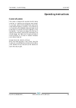
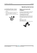
Page 43: ...o wheel steering mode is enabled Raising and Lowering the Outriggers Push the top of the rocker switch to extend lower the outriggers Push the bottom of the rocker switch to raise retract the outrigger Levelling the chassis Push the right side of the rocker switch to lower the right side of the chassis Push the left side of the rocker switch to lower the left side of the chassis Emergency Exit Pul...

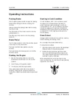
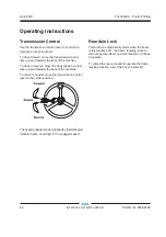
Page 44: ...ssion control lever up and towards the back of the machine To return to neutral move the transmission control lever to the center position Thespeedengagementissignalledbythededicated indicator lights according to the engaged speed Rear Axle Lock This function automatically starts when the boom is raised above 50 the frame levelling function will not operate Boom and fork functions continue to oper...

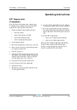
Page 45: ...switch high exhaust system temperature indicator light 9 switches on with a solid light and the engine revs up to 1 200 rpm vii Keep clear of the exhaust muffler area viii Don t leave the machine unattended ix Signpost the area x Machine must remain parked outdoors for 30 minutes approximately xi In case of need regeneration can be stopped by pushing the DPF switch and then restarted xii Once the ...

Page 46: ...ot lowered the outriggers lower the outriggers and use the load chart for outriggers down If the outriggers are down 2 Move the machine closer to the loading or pick point so that the weight of the load will meet the load chart specifications 3 Divide the load into smaller pieces so that each piece meets the load chart specifications 4 Obtain a larger machine capable of handling the load within sp...

Page 47: ... the front to back level indicator is not at 0 degrees 6 Gradually move the controller to raise and extend the boom to the required height 7 Gradually move the controller to lower and extend the boom into final position Lower the load until the weight is completely off the forks Do not apply a downward force with the forks 8 Gradually move the controller to raise and retract the boom This will bri...

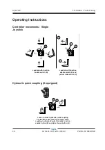
Page 48: ...tick with function enable switch B and yellow roller switch C C C C Controller movements Single Joystick Lock or unlock hydraulic quick coupling by simultaneously pressing hydrulic quick coupling lock unlock switch joystick function enable button B and white thumb button A Hydraulic quick coupling if equipped Operating Instructions ...

Page 49: ...loading cycle it does not address the risks associated with pick and carry operations The LMS is an electronic system including several sensing components and may be subject to component failure These electronic components are constantly monitored by the LMS so the system is able to notify the operator when a fault occurs alarms and warnings describing the type of fault are communicated to the ope...

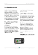
Page 50: ...play can also be used to troubleshoot machine faults associated with LMS i e boom operation joystick outrigger and chassis tilting functionality There are two main screens used to display information about the condition of the machine during normal operation Function buttons 1 2 Functionality of these buttons depends on the screen being displayed In the home screen function buttons on the left han...

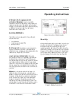
Page 51: ...mit for a particular operator A login screen is displayed after the LMS boot up sequence is complete which prompts the user to login before machine s boom functions are enabled iButton This access method operates in a similar manner to login access except that an iButton is required to operate the machine s boom functions An iButton is an electronic coded key which contains user data The optional ...

Page 52: ...attachment on the display corresponds to the attachment being used Begin operation as per instructions in this manual Shut Down After the ignition is turned off the system remains in stand by mode for a period of 30 minutes During this time the display screen is turned off but the system turns on when the ignition is turned on accessories After 30 minute stand by time the system shuts down and wil...

Page 53: ...ius and retract the telescopic boom before lowering the load Release the joystick and function enable button Turn override key switch A Figure8 Figure 8 Override key switch A LMS override is enabled when the LMS over ride icon appears on the home screen item 17 on Figure 9 Primary Home Screen This is the default screen displayed during opera tion of the machine It displays the most relevant inform...

Page 54: ...is active The icon will disappear when the alarm condition has been cleared Overload icon 16 Overload icon appears when actual load has exceeded rated capacity Override icon 17 The override icon appears when LMS override function is in use Time date 18 Current time date This value toggles between time and date every 10 seconds Machine status 19 This icon indicates the position of job site road pla...

Page 55: ...ng to the right a negative value indicates the machine is tilting to the left Chassis tilt angle indicator 38 Graphical display of chassis tilt angle direction Alarms and warnings 39 Active alarms and warnings automatically scroll through this window A blank window indicates there are no active alarms or warnings The LMS override key should be kept by the site manager or the person responsible for...

Page 56: ...April 2019 54 GTH 4014 AU GTH 4018 AU Part No 57 0009 0729 First Edition Fourth Printing Figure 11 Display secondary home screen Operating Instructions ...

Page 57: ...agement System Indicator Christmas Tree Lights if equipped This device fitted outside the cabin is connected to the LMS and shows the same LED sequence which appears on the LMS display Load Management System Override Key Switch This switch allows the override of the LMS in order to recover the machine when it is stuck after the load limiting system has triggered in case of main machine failures re...

Page 58: ... button on the joystick the hydrulic quick coupling lock unlock button the function enable button on the joystick and shifting the joystick to the right 7 Tilt the attachment frame forward and lower the boom to release the attachment upper lock 8 Move back with the machine and drive to the new attachment to be coupled 9 Hold the frame tilted forward and hook the upper lock of the new attachment 10...

Page 59: ...er leads in the reverse order Driving on a slope When the machine is loaded always travel with the load uphill When the machine is unloaded travel with the forks or attachment downhill On steep terrain drive only up and down hill and always keep the machine in gear Do not turn across slope when machine is traveling up or down a slope Limit travel path and speed according to the condition of the gr...

Page 60: ...e Make sure that lights horn and turn signals are in working order The drive speed of the machine will depend on the engine rpm and gear selected Driving on public loads is only allowed with an unloaded machine Do not use the machine to tow trailers Engine Condition Indicator If the Alert indicator light and or the Engine Critical Fault indicator light switches on contact service personnel After E...

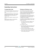
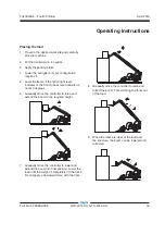
Page 61: ...tion may result in serious damage to thetransmission Whenpossible repairthemachine on site When the machine must be towed 1 Disable the parking brake 2 Set the transmission to neutral see next page 3 Select the two wheel steer 4 Connect a rigid draw bar to one of the two tie down points present on the front axle 5 When possible start the engine and use the hydraulic drive and the braking system 6 ...

Page 62: ...rasmission to neutral To set the trasmission to neutral 1 Unscrew the screws M8x25 n 1 2 Remove the cover n 2 3 Move the pin with a M10 extractor until both switches are activated 4 Reassemble the components Tightening torque of screws n 1 is 23Nm 5 15 This emergency operation must be performed with the engine turned off and on level ground Operating Instructions ...

Page 63: ...se of extended inactivity of the machine follow the above precautions Additionally Wash the machine thoroughly For better cleaning remove grills and protection casings Carefully dry all machine parts by blowing with compressed air Lubricate the machine thoroughly Do a walk around inspection and replace any worn or damaged part Re paint any worn or damaged part Remove the battery smear its terminal...

Page 64: ...me water and a sponge Do not use water at high pressure After washing dry with a clean cloth Washing the engine Beforewashingtheengine protecttheairintakefilter to prevent water from entering the circuit If the machine is to be used in a marine or equivalent environment protect it against salt deposits with an adequate treatment to prevent rust formation Machine disposal At the end of the machine ...

Page 65: ...ding and securing construction and lifting equipment for international shipment Only qualified operators should move the machine on or off the truck The transport vehicle must be parked on a level surface The transport vehicle must be secured to prevent rolling while the machine is being loaded Before loading for transport make sure the deck ramps and machine tires are free of mud snow and ice Fai...

Page 66: ...red if equipped Prior to loading level the telehandler and retract the boom Retract the outriggers Use a spotter to load and unload the telehandler Keep the boom as low as possible when loading and unloading Set the parking brake Securing the Chassis Use chains of ample load capacity Use a minimum of 6 chains There are 8 tie down points four on each side of the machine Fully lower the forks or att...

Page 67: ...city loading surfaces and straps or lines are sufficient to withstand the machine weight See the serial label for the machine weight Lifting Instructions Fully lower and retract the boom Retract the outriggers Determine the center of gravity of your machine using the picture on this page Remove all loose items on the machine Attach the rigging only to the designated lifting points on the machine A...

Page 68: ...t tools will be required to perform this procedure Indicates that new parts will be required to perform this procedure Indicates that a cold engine will be required to perform this procedure Check the Tire Pressure Tip over hazard An over inflated tire can explode which may compromise machine stability and cause the machine to tip over Tip over hazard The use of temporary flat tire repair products...

Page 69: ...ns levels The Stage III B diesel engine must be operated using only Ultra Low Sulfur Fuel The sulphur content of this fuel must be lower than 15 PPM Tank 170 L 45 gal Perkins 1104D E44T STAGE III A Fuel Type Diesel Maintenance Check the Hydraulic Oil Level Maintaining the hydraulic oil at the proper level is essential to machine operation Improper hydraulic oil levels can damage hydraulic componen...

Page 70: ...ds is essential to workplace visibility 1 Visually inspect all mirrors to ensure they are working properly and clean and free from debris Check the Battery Proper battery condition is essential to good machine performance and operational safety Improper fluid levels or damaged cables and connections can result in component damage and hazardous conditions Electrocution hazard Contact with hot or li...

Page 71: ...ction procedure is completed Use the step by step procedures in this section to learn how to perform these inspections If any inspection receives an N tag and remove the machine from service repair and re inspect it After repair place a check in the R box Checklist A Y N R A 1 Manuals and decals A 2 Pre operation inspect A 3 Function tests A 4 Lubricate the boom A 5 Engine maintenance Perkins mode...

Page 72: ...esult in hazardous operating conditions 1 Check to make sure that the operator s and safety manuals are present and complete in the storage container in the operator s compartment 2 Examine the pages of each manual to be sure that they are legible and in good condition Result The operator s manual is appropriate for the machine and all manuals are legible and in good condition Result The operator ...

Page 73: ...s designed to discover if anything is apparently wrong with a machine before the operator performs the function tests The Pre operation Inspection also serves to determine if routine maintenance procedures are required A 3 Perform Function Tests Genie specifications require that this procedure be performed every 8 hours or daily whichever comes first Completing the function tests is essential to s...

Page 74: ...kes contact with the number 2 boom tube lower wear pads 4 Apply a thin layer of grease to the underside of the number 2 boom tube where it makes contact with the number 1 boom tube lower wear pads 5 Lubricate the top and side boom tube wear pads 6 Return the boom to the stowed position To lubricate the boom of GTH 4018 1 Fully extend and raise the boom then retract the boom checking to ensure it o...

Page 75: ...urs or daily whichever comes first Engine oil level check Coolant level check add Fuel system filter water separator drain Engine tightness check for leaks Exhaust system check for leaks Required maintenance procedures and additional engine information is available in the Perkins1104DOperationandMaintenanceManual Perkins part number SEBU8172 02 Perkins1104D EOperationandMaintenanceManual Genie par...

Page 76: ...M Front Rear Axle Maintenance and Repair Instructions Genie part number Genie Instructions Library 57 4700 0023 A 8 Perform Axle Maintenance Note Axle specifications require that this one time procedurebeperformedafter150hoursofoperation Change axle oil Clean magnetic oil plugs Oil breather clean Grease axle if required Required maintenance procedures and additional axle information is available i...

Page 77: ...it and replace attachments onthemachinecanbefoundinsection QuickAttach Instructions Attachments Genie Approved Attachments List Floating Forks part number AUS10098 Fixed Hook part number AUS10011 2 m Jib part number AUS10020 Side Shift Forks part number AUS10025 Extended Forks part number AUS10077 Fork Rotator part number AUS10052 800 L Bucket 2400 mm wide part number AUS10007 900 L 4 in 1 Bucket ...

Page 78: ... Safety Do not oscillate the load Do not drag hooked loads Lift the load before extending the boom Operation Fork the hook and hold it in position by means of the locking cylinder All loads must be bridled with special textile slings or chains in compliance with all pertinent regulations To handle the load raise and rotate the telescopic boom of the handler Maintenance Visually check the hook for ...

Page 79: ...oid abrupt acceleration or deceleration Avoid load oscillations and especially do not move the load from the vertical pull line Do not pull crosswise and do not tow Operation Couple the jib and hold it in position by means of the locking cylinder All loads must be lifted with slings or chains in compliance with all relevant regulations To handle the load raise and rotate the telescopic boom of the...

Page 80: ...ity of shifting the load to the side by 100mm Safety Strictly obey the general safety precaution given in section Safety Do not load loose materials Do not move stacked pallets Operation To adjust the tilting operate the rotation lever of the attachment coupling frame to side shift operate the attachment locking le ver after connecting the hoses of the attachment to the quick couplings Maintenance...

Page 81: ... Do not use for digging operations Application Quick coupling attachment for moving soil sand debris grains etc Safety Strictly obey the general safety precautions given in section Safety Operation To load unload the material operate the rotation lever of the attachment holding plate When using a bucket load the material only when the boom is completely retracted and puch against the heap with str...

Page 82: ...hange As a result extreme caution in transporting and lifting or placing the load must be observed to minimize the potential for the load to move Overturning Hazards Do not lift a suspended load without the proper and legible load capacity chart for the attachment telehandler combination you are using Do not permit the load to swing freely Always properly tether loads to restrict movement Driving ...

Page 83: ...e attempting to re position the load Do not attempt to cross inclines as the load center will move towards the tipping line thereby reducing stability Only climb or descend inclines with extreme care as the load center will move towards the tipping line thereby reducing stability Do not park on a slope When driving on a rise with loaded material proceed in forward gear and travel with load in the ...

Page 84: ...onstant communication verbal or hand and be in visual contact with the operator at all times Crush Hazards Never allow the signal person dogger to come between the suspended load and another object such as the telehandler itself Attachments Falling Object Hazards Do not raise the load into the fall zone shown Do not operate the machine while people are under the load or in the fall zone Do not sus...

Page 85: ... above 300mm clear of the ground Be sure that all boom and attachment movements are performed as slow as practical to avoid swinging of the load Travelling Be sure that the path of travel is level and capable of supporting the telehandler with its load Ground side slope must not exceed the values listed on the load chart Keep the boom and load as low as practical while maintaining visibility in th...

Page 86: ...load until it is safely supported Once the load has been landed continue to lower the boom until the rigging and tethers can be removed Signal Person Dogger A signal person dogger is recommended when The point of operation meaning the load travel or the area near or at load placement is not in full view of the operator When the equipment is traveling the view in the direction of travel is obstruct...

Page 87: ...SIGNAL Hoisting raise 2 short Hoisting lower 1 long Luffing boom up 3 short Luffing boom down 4 short Slewing right 1 long 2 short Slewing left 1 long 1 short Jib trolley out telescoping boom extend 1 long 3 short Jib trolley in telescoping boom retract 1 long 4 short Travel and traverse Not applicable STOP 1 short CREEP SPEED APPROPRIATE HAND SIGNAL FOR MOTION WITH HAND OPENING AND CLOSING ...

Page 88: ...dy 0 32 m s2 Maximum wheel load with rated load 6385 kg Maximum outrigger pad with rated load 4 6 kg cm2 Reversing camera pitch angle 51 below horizontal GTH 4018 Height stowed 2 44 m Length stowed to attachment frame 6 57 m Width standard tires 2 42 m Wheelbase 2 95 m Ground clearance center 0 35 m Weight 12 640 kg Working fork height maximum 17 61 m Horizontal reach maximum 13 27 m Reach at maxi...

Page 89: ...729 GTH 4014 AU GTH 4018 AU 87 GTH 4014 AU Standard Forks Load Charts Refer to load charts provided in cabin for comprehensive operating restrictions e g pick and carry configuration allowable slope for various operating modes and in service wind speed rating ...

Page 90: ...April 2019 88 GTH 4014 AU GTH 4018 AU Part No 57 0009 0729 First Edition Fourth Printing Load Charts GTH 4014 AU Standard Forks ...

Page 91: ...April 2019 First Edition Fourth Printing Part No 57 0009 0729 GTH 4014 AU GTH 4018 AU 89 GTH 4014 AU Fixed Hook Load Charts ...

Page 92: ...April 2019 90 GTH 4014 AU GTH 4018 AU Part No 57 0009 0729 First Edition Fourth Printing GTH 4014 AU Fixed Hook Load Charts ...

Page 93: ...April 2019 First Edition Fourth Printing Part No 57 0009 0729 GTH 4014 AU GTH 4018 AU 91 Load Charts GTH 4014 AU 2 m Jib ...

Page 94: ...April 2019 92 GTH 4014 AU GTH 4018 AU Part No 57 0009 0729 First Edition Fourth Printing Load Charts GTH 4014 AU 2 m Jib ...

Page 95: ...April 2019 First Edition Fourth Printing Part No 57 0009 0729 GTH 4014 AU GTH 4018 AU 93 Load Charts GTH 4014 AU Side Shift Forks ...

Page 96: ...April 2019 94 GTH 4014 AU GTH 4018 AU Part No 57 0009 0729 First Edition Fourth Printing Load Charts GTH 4014 AU Side Shift Forks ...

Page 97: ...April 2019 First Edition Fourth Printing Part No 57 0009 0729 GTH 4014 AU GTH 4018 AU 95 Load Charts GTH 4014 AU Extended Forks ...

Page 98: ...April 2019 96 GTH 4014 AU GTH 4018 AU Part No 57 0009 0729 First Edition Fourth Printing Load Charts GTH 4014 AU Extended Forks ...

Page 99: ...April 2019 First Edition Fourth Printing Part No 57 0009 0729 GTH 4014 AU GTH 4018 AU 97 Load Charts GTH 4014 AU Fork Rotator ...

Page 100: ...April 2019 98 GTH 4014 AU GTH 4018 AU Part No 57 0009 0729 First Edition Fourth Printing Load Charts GTH 4014 AU Fork Rotator ...

Page 101: ...April 2019 First Edition Fourth Printing Part No 57 0009 0729 GTH 4014 AU GTH 4018 AU 99 Load Charts GTH 4014 AU GP Bucket 800 L ...

Page 102: ...April 2019 100 GTH 4014 AU GTH 4018 AU Part No 57 0009 0729 First Edition Fourth Printing Load Charts GTH 4014 AU GP Bucket 800 L ...

Page 103: ...April 2019 First Edition Fourth Printing Part No 57 0009 0729 GTH 4014 AU GTH 4018 AU 101 GTH 4014 AU 4 in 1 Bucket 900 L Load Charts ...

Page 104: ...April 2019 102 GTH 4014 AU GTH 4018 AU Part No 57 0009 0729 First Edition Fourth Printing GTH 4014 AU 4 in 1 Bucket 900 L Load Charts ...

Page 105: ...729 GTH 4014 AU GTH 4018 AU 103 GTH 4018 AU Standard Forks Load Charts Refer to load charts provided in cabin for comprehensive operating restrictions e g pick and carry configuration allowable slope for various operating modes and in service wind speed rating ...

Page 106: ...April 2019 104 GTH 4014 AU GTH 4018 AU Part No 57 0009 0729 First Edition Fourth Printing Load Charts GTH 4018 AU Standard Forks ...

Page 107: ...April 2019 First Edition Fourth Printing Part No 57 0009 0729 GTH 4014 AU GTH 4018 AU 105 GTH 4018 AU Fixed Hook Load Charts ...

Page 108: ...April 2019 106 GTH 4014 AU GTH 4018 AU Part No 57 0009 0729 First Edition Fourth Printing GTH 4018 AU Fixed Hook Load Charts ...

Page 109: ...April 2019 First Edition Fourth Printing Part No 57 0009 0729 GTH 4014 AU GTH 4018 AU 107 GTH 4018 AU 2 m Jib Load Charts ...

Page 110: ...April 2019 108 GTH 4014 AU GTH 4018 AU Part No 57 0009 0729 First Edition Fourth Printing GTH 4018 AU 2 m Jib Load Charts ...

Page 111: ...April 2019 First Edition Fourth Printing Part No 57 0009 0729 GTH 4014 AU GTH 4018 AU 109 GTH 4018 AU Side Shift Forks Load Charts ...

Page 112: ...April 2019 110 GTH 4014 AU GTH 4018 AU Part No 57 0009 0729 First Edition Fourth Printing GTH 4018 AU Side Shift Forks Load Charts ...

Page 113: ...April 2019 First Edition Fourth Printing Part No 57 0009 0729 GTH 4014 AU GTH 4018 AU 111 GTH 4018 AU Extended Forks Load Charts ...

Page 114: ...April 2019 112 GTH 4014 AU GTH 4018 AU Part No 57 0009 0729 First Edition Fourth Printing GTH 4018 AU Extended Forks Load Charts ...

Page 115: ...April 2019 First Edition Fourth Printing Part No 57 0009 0729 GTH 4014 AU GTH 4018 AU 113 GTH 4018 AU Fork Rotator Load Charts ...

Page 116: ...April 2019 114 GTH 4014 AU GTH 4018 AU Part No 57 0009 0729 First Edition Fourth Printing GTH 4018 AU Fork Rotator Load Charts ...

Page 117: ...April 2019 First Edition Fourth Printing Part No 57 0009 0729 GTH 4014 AU GTH 4018 AU 115 GTH 4018 AU GP Bucket 800 L Load Charts ...

Page 118: ...April 2019 116 GTH 4014 AU GTH 4018 AU Part No 57 0009 0729 First Edition Fourth Printing GTH 4018 AU GP Bucket 800 L Load Charts ...

Page 119: ...April 2019 First Edition Fourth Printing Part No 57 0009 0729 GTH 4014 AU GTH 4018 AU 117 GTH 4018 AU 4 in 1 Bucket 900 L Load Charts in ...

Page 120: ...April 2019 118 GTH 4014 AU GTH 4018 AU Part No 57 0009 0729 First Edition Fourth Printing GTH 4018 AU 4 in 1 Bucket 900 L Load Charts in ...

Page 121: ... y B d e t u b i r t s i D www genielift com ...

Reviews: