background image

Operator's Manual

Fifth Edition • Second Printing

Part No. T113597

S-100  • S-105 • S-120 • S-125

15

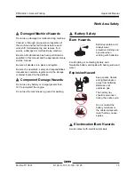
  Damaged Machine Hazards

Do not use a damaged or malfunctioning machine.

Conduct a thorough pre-operation inspection of
the machine and test all functions before each
work shift. Immediately tag and remove from
service a damaged or malfunctioning machine.

Be sure all maintenance has been performed as
specified in this manual and the appropriate Genie
service manual.

Be sure all decals are in place and legible.

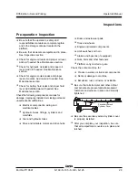
Be sure the operator's, safety and responsibilities
manuals are complete, legible and in the storage
container located on the platform.

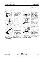
  Component Damage Hazards

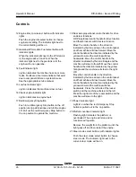
Do not use any battery or charger greater than
12V to jump-start the engine.

Do not use the machine as a ground for welding.

  Battery Safety

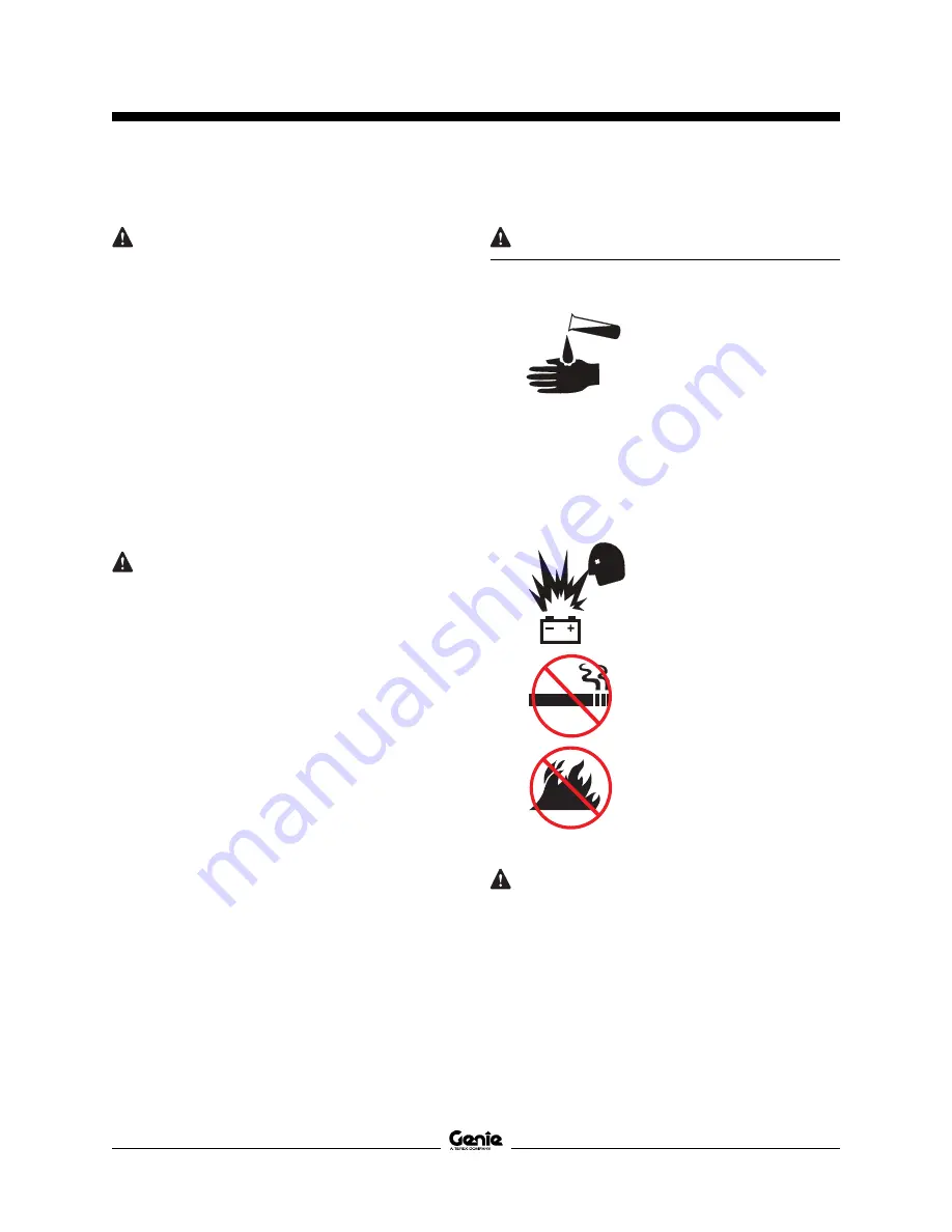
Burn Hazards

Batteries contain acid.
Always wear
protective clothing and
eye wear when
working with batteries.

Avoid spilling or contacting battery acid.
Neutralize battery acid spills with baking soda and
water.

Explosion Hazard

Keep sparks, flames
and lighted tobacco
away from batteries.
Batteries emit
explosive gas.

The battery tray
should remain open
during the entire cycle.

Do not contact the
battery terminals or
the cable clamps with
tools that may cause
sparks.

  Electrocution/Burn Hazards

Avoid contact with electrical terminals.

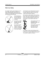
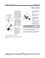
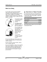
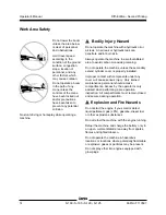
Work Area Safety

Summary of Contents for Genie S-100

Page 1: ......

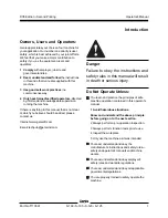
Page 2: ...ese safety rules and operating instructions before operating this machine Only trained and authorized personnel shall be permitted to operate this machine This manual should be considered a permanent part of your machine and should remain with the machine at all times If you have any questions call Genie Industries Contents Page Introduction 1 Symbol and Hazard Pictorials Definitions 3 GeneralSafe...

Page 3: ... obey employer s safety rules and worksite regulations You read understand and obey all applicable governmentalregulations You are properly trained to safely operate the machine Owners Users and Operators Genie appreciates your choice of our machine for your application Our number one priority is user safety which is best achieved by our joint efforts We feel that you make a major contribution to ...

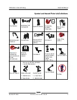
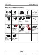
Page 4: ...they may damage the safety sign material Hazard Classification Genie uses symbols color coding and signal words to identify the following Safety alert symbol used to alert you to potential personal injury hazards Obey all safety messages that follow this symbol to avoid possible injury or death Indicates a hazardous situation which if not avoided will result in death or serious injury Indicates a ...

Page 5: ... moving parts Maintainrequired clearance Keep away from path of moving platform No smoking No flame Stopengine Do not overload platform Welder powersupply weighs 75 lbs 34 kg Tip over Hazard Onlytrained maintenance personnelshould access compartments Readthe operator s manual Platformdownhill 1 Retract boom 2 Lower boom Platform uphill 1 Lower boom 2 Retract boom Tip over Hazard Recovery procedure...

Page 6: ...wn instructions Tie down instructions Electrocution Hazard ExplosionHazard Do not use ether or other high energystarting aids on machines equippedwith glow plugs FireHazard Explosion Burn Hazard Keep all open flames and sparks away Pressure rating for air line to platform Read service manual Voltage rating for power to platform Replace tires with same tire Replace extension cylinder cover before o...

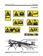
Page 7: ...Operator s Manual Fifth Edition Second Printing PartNo T113597 S 100 S 105 S 120 S 125 5 General Safety ...

Page 8: ...Operator s Manual Fifth Edition Second Printing 6 S 100 S 105 S 120 S 125 PartNo T113597 General Safety ...

Page 9: ...Operator s Manual Fifth Edition Second Printing PartNo T113597 S 100 S 105 S 120 S 125 7 General Safety ...

Page 10: ...ts must wear a safety belt or harness in accordance with governmental regulations Attach the lanyard to the anchor provided in the platform Operators must comply with employer job site and governmental rules regarding the use of personal protectiveequipment All PFPE must comply with applicable governmental regulations and must be inspected and used in accordance with the PFPE manufacturer sinstruc...

Page 11: ...age RequiredClearance 0 to 50KV 3 0 m 50KV to 200KV 4 6 m 200KV to 350KV 6 1 m 350KV to 500KV 7 6 m 500KV to 750KV 10 6 m 750KV to 1000KV 13 7 m Keep away from the machine if it contacts energized power lines Personnel on the ground or in the platform must not touch or operate the machine until energized power lines are shut off Do not use the machine as a ground for welding unless the machine is ...

Page 12: ...machine is on a severe slope If the tilt alarm sounds while the boom is lowered Do not extend rotate or raise the boom above horizontal Move the machine to a firm level surface before raising the platform If the tilt alarm sounds while the boom is raised Use extreme caution Identify the condition of the boom on the slope as shown below Follow the steps to lower the boom before moving to a firm lev...

Page 13: ...neven terrain unstable surfaces or other hazardous conditions with the boom raised or extended Do not use the machine as a crane Do not push the machine or other objects with the boom Do not contact adjacent structures with the boom Do not tie the boom or platform to adjacent structures Do not place loads outside the platform perimeter Do not alter or disable the limit switches Do not push off or ...

Page 14: ...m can increase the weight in the platform and the surface area of the platform or the load Do not place or attach overhanging loads to any part of this machine Do not place ladders or scaffolds in the platform or against any part of this machine Do not transport tools and materials unless they are evenly distributed and can be safely handled by person s in the platform Do not use the machine on a ...

Page 15: ... entry gate before operating Do not enter or exit the platform unless the machine is in the stowed position and the platform is at ground level Collision Hazards Be aware of limited sight distance and blind spots when driving or operating Be aware of the boom position and tailswing when rotating the turntable Check the work area for overhead obstructions or other possible hazards Be aware of crush...

Page 16: ...ell ventilated area to avoid carbon monoxide poisoning Do not operate the machine unless the secondary extend cylinder cover is properly installed Improper contact with components under any cover will cause serious injury Only trained maintenance personnel should access compartments Access by the operator is only advised when performing a pre operation inspection All compartments must remain close...

Page 17: ...legible and in the storage container located on the platform Component Damage Hazards Do not use any battery or charger greater than 12V to jump start the engine Do not use the machine as a ground for welding Battery Safety Burn Hazards Batteries contain acid Always wear protective clothing and eye wear when working with batteries Avoid spilling or contacting battery acid Neutralize battery acid s...

Page 18: ...orm capacity and must be factored into the total platform load The welder power supply weighs 34 kg Do not operate the welder unless a fire extinguisher is immediately available for instant use per OSHA regulation 1926 352 d Weld Line to Platform Safety Read understand and obey all warnings and instructions provided with the welding power unit Do not connect weld leads or cables unless the welding...

Page 19: ...t of the platform with an overhanging load Do not cause a horizontal force or side load to the machine by raising or lowering a fixed or overhangingload Electrocution Hazard Keep pipes away from all energized electrical conductors Panel Cradle Safety Read understand and obey all warnings and instructions provided with the panel cradles Do not exceed the rated platform capacity The combined weight ...

Page 20: ...ct a safe parking location firm level surface clear of obstruction and traffic 2 Retract and lower the boom to the stowed position 3 Rotate the turntable so that the boom is between the wheels at the circle end of the machine 4 Turn the key switch to the off position and remove the key to secure from unauthorized use 5 Chock the wheels ...

Page 21: ...05 S 120 S 125 19 1 Circle end tire yellow arrow 2 Square endtire bluearrow 3 Groundcontrols 4 Boom 5 Platform controls 6 Platform 7 Jib boom S 105 and S 125 8 Lanyard anchorage point 9 Slidingmid rail 10 Manualstoragecontainer 11 Foot switch S 105 S 125 S 100 S 120 Legend ...

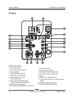
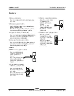
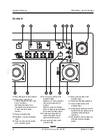
Page 22: ...ct button 7 LCD readout screen 8 Diesel models Glow plug button Gasoline LPG models Choke button 9 Red Emergency Stop button 10 Key switch for off platform ground selection 11 Engine start button 12 Emergency power button 13 High speed function enable button 14 Low speed function enable button 15 Alarm 16 Platform level up down buttons 17 S 105 and S 125 models Jib boom up down buttons 18 Platform...

Page 23: ...o the ground position and the ground controls will operate Turn the key switch to the platform position and the platform controls will operate 1 Boom down button Push the boom down button and the boom will lower 2 Boom extend retract buttons Push the boom extend button and the boom will extend Push the boom retract button and the boom will retract 3 Boom up button Push the boom up button and the b...

Page 24: ...n the ground control panel to operate at low speed 15 Alarm 16 Platform level up down buttons Push the platform level up button and the level of the platform will raise Push the platform level down button and the level of the platform will lower 17 S 105 and S 125 models Jib boom up down buttons Push the jib boom up button and the jib boom will raise Push the jib boom down button and the jib boom ...

Page 25: ...light 16 Check engine indicator light Platform Control Panel 1 Platform rotate switch 2 Platform level switch 3 Platform not level indicator light 4 Machine not level indicator light 5 Retract boom indicator light 6 Raise boom indicator light 7 Hornbutton 8 Generatorbuttonwith indicator light option 2 6 5 7 8 9 10 24 25 26 27 28 29 4 3 9 Emergency power button with indicator light 10 Diesel models...

Page 26: ... 15 14 17 18 19 16 20 21 22 23 22 Drive select button with indicator lights Machine on incline symbol Lowrangeoperationfor inclines Machine on level surface symbol High range operation for maximum drive speed 23 Singleaxisproportional control handle for boom extend retractfunction 24 Axle extend button with indicator light 25 Axle retract button with indicator light 26 Used for optional equipment ...

Page 27: ... extending raise the boom until the indicator light goes out 7 Horn button Push the horn button and the horn will sound Release the horn button and the horn will stop 8 Generator button with indicator light option Push the generator button to activate the generator The light will be on Push the button again to turn off the light and restore machine functions 9 Emergency power button with indicator...

Page 28: ...ocker switch for steer function Move the control handle in the direction indicated by the blue arrow on the control panel and the machine will drive forward Move the control handle in the direction indicated by the yellow arrow and the machine will drive backwards Move the control handle in the direction indicated by the blue triangle and the machine will steer to the left Move the control handle ...

Page 29: ...e indicator light will flash while the axles are retracting and stay on when the axles are fully retracted 26 Used for optional equipment 27 Drive enable button with indicator light Light on indicates that the primary boom has moved past either circle end wheel and the drive function is turned off To drive push the drive enable button and slowly move the drive steer control handle off center 28 Du...

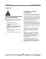
Page 30: ...designed to discover if anything is apparently wrong with a machine before the operator performs the function tests The pre operation inspection also serves to determine if routine maintenance procedures are required Only routine maintenance items specified in this manual may be performed by the operator Refer to the list on the next page and check each of the items If damage or any unauthorized v...

Page 31: ... or areas for damage improperly installed or missing parts and unauthorizedmodifications R Electrical components wiring and electrical cables R Hydraulic hoses fittings cylinders and manifolds R Fuel and hydraulic tanks R Drive and turntable motors and drive hubs R Boom and axle wear pads R Tires and wheels R Engine and related components R Limit switches and horn R Alarms and beacons if equipped ...

Page 32: ...ons to test all machine functions A malfunctioning machine must never be used If malfunctions are discovered the machine must be tagged and removed from service Repairs to the machine may only be made by a qualified service technician according to the manufacturer s specifications After repairs are completed the operator must perform a pre operation inspection and function tests again before putti...

Page 33: ...e Start this test with the axles retracted 11 At the ground controls push and hold a function enable speed select button and push the boom up button Result The boom should raise to 10 above horizontal and then stop The boom should not raise above the limit switch unless both axles are extended 12 Push and hold a function enable speed select button and push the boom down button Result The boom shou...

Page 34: ... function button Result All boom and platform functions should operate through a full cycle The descent alarm if equipped should sound while the boom is lowering TestEmergencyControls 19 Turn the key switch to ground control and shut the engine off 20 Pull out the red Emergency Stop button to the on position 21 Simultaneously push and hold the emergency power button and push each boom function but...

Page 35: ...layed 29 Extend the boom and observe the LCD screen Result The LCD screen should display at 0 0 75 100 100 30 Retract the boom At the Platform Controls Test Emergency Stop 31 Turn the key switch to platform control 32 Push in the platform red Emergency Stop button to the off position Result The engine should turn off and no functions should operate 33 Pull out the red Emergency Stop button and res...

Page 36: ...oordinated steer 53 Press down the foot switch Test the Foot Switch 36 Push in the platform red Emergency Stop button to the off position 37 Pull out the red Emergency Stop button to the on position but do not start the engine 38 Press down the foot switch and attempt to start the engine by pushing the engine start button Result The engine should not start 39 Do not press down the foot switch and ...

Page 37: ...hine begins to move then return the handle to the center position Result The machine should move in the direction that the yellow arrow points on the drive chassis then come to an abrupt stop Note The brakes must be able to hold the machine on any slope it is able to climb Test the Drive Enable System 58 Press down the foot switch and lower the boom to the stowed position 59 Rotate the turntable u...

Page 38: ...e machine will travel 12 2 m in 40 seconds If the drive speed with the boom raised or extended exceeds 30 cm per second immediately tag and remove the machine from service 68 Raise the boom to horizontal Extend the boom as far as it will go 69 Slowly move the drive control handle to the full drive position Result The maximum achievable drive speed with the boom fully extended should not exceed 18 ...

Page 39: ...te Unless You learn and practice the principles of safe machine operation contained in this operator s manual 1 Avoid hazardous situations 2 Always perform a pre operation inspection 3 Always perform function tests prior to use 4 Inspecttheworkplace Know and understand the workplace inspection before going on to the next section 5 Only use the machine as it was intended Fundamentals The workplace ...

Page 40: ...spection for Decals with Symbols Determine whether the decals on your machine have words or symbols Use the appropriate inspection to verify that all decals are legible and in place Part No Description Quantity 72147 Cosmetic Genie S 100 1 72148 Cosmetic Genie S 105 1 72149 Cosmetic S 100 1 72150 Cosmetic S 105 1 72152 Label Range of Motion S 100 and S 105 1 82240 Label Noise Level 1 82422 Label W...

Page 41: ...Operator s Manual Fifth Edition Second Printing PartNo T113597 S 100 S 105 S 120 S 125 39 Inspections Shading indicates decal is hidden from view i e under covers ...

Page 42: ...osion Hazard 1 114252 Label Tip Over Hazard Limit Switch 4 114473 Label Tip Over Hazard Tilt Alarm 1 133067 Label Electrocution Hazard 4 133205 Label Electrocution Hazard Battery 1 Inspection for Decals with Symbols Determine whether the decals on your machine have words or symbols Use the appropriate inspection to verify that all decals are legible and in place This inspection is a continuation f...

Page 43: ...Operator s Manual Fifth Edition Second Printing PartNo T113597 S 100 S 105 S 120 S 125 41 Inspections Shading indicates decal is hidden from view i e under covers ...

Page 44: ... to follow all the safety rules and instructions in the operator s safety and responsibilities manuals Using the machine for anything other than lifting personnel along with their tools and materials to an aerial work site is unsafe and dangerous Only trained and authorized personnel should be permitted to operate a machine If more than one operator is expected to use a machine at different times ...

Page 45: ...esired position 2 Be sure both ground and platform control red Emergency Stop buttons are pulled out to the on position Diesel models 3 Press the engine start button Note In cold conditions 10 C and below push and hold the glow plug button for 10 to 20 seconds before starting the engine Gasoline LPG models 3 Choose fuel by pressing the fuel select button 4 Push the engine start button Note In cold...

Page 46: ...ropriate function control handle or toggle switch or press the appropriate button according to the markings on the control panel To Steer 1 Press down the foot switch 2 Select the steer mode by pressing a steer mode button The indicator light next to the current steer mode will be on 3 Slowly move the drive steer control handle in the direction of the blue or yellow triangle OR press the thumb roc...

Page 47: ...mine the slope grade Measure the slope with a digital inclinometer OR use the following procedure You will need carpenter s level straight piece of wood at least 1 m long tape measure Lay the piece of wood on the slope At the downhill end lay the level on the top edge of the piece of wood and lift the end until the piece of wood is level While holding the piece of wood level measure the distance f...

Page 48: ...witch symbol foot switch activated high idle Turtle symbol low idle Rabbit symbol high idle Check Engine Light Light on and engine stopped Tag the machine and remove from service Light on and engine still running Contact service personnel within 24 hours Operating Envelope Indicator Lights The operating envelope indicator lights will come on to notify the operator that a function has been interrup...

Page 49: ...indicator light is off Restart the engine to continue operation Raise Boom indicator light is flashing Use the Auxiliary Power Unit at the platform to raise the boom until the indicator light is off Restart the engine to continue operation If the Auxiliary Power Unit at the platform does not function a trained operator on the ground will need to lower the platform from the ground controls Please s...

Page 50: ...able Rotate Direction Switch 92 Turntable Rotate Valve 94 Turntable Speed 98 Platform Controller Platform Level Sensor 99 Platform Level Direction Switch 110 Platform Rotate Direction Switch 117 Platform Overload Switches 119 Multi Function Valve 120 Safety Switch P3 121 Safety Switch P6R1 Fault Source ID Description 122 Safety Switch P6R2 123 Safety Switch P7 124 Safety Switch P7R 125 Safety Swit...

Page 51: ...Use 1 Select a safe parking location firm level surface clear of obstruction and traffic 2 Retract and lower the boom to the stowed position 3 Rotate the turntable so that the boom is between the circle end wheels 4 Turn the key switch to the off position and remove the key to secure from unauthorized use 5 Chock the wheels ...

Page 52: ...cradle on each side of the platform Refer to the illustration on the left Make sure the bottom of the pipe cradle tube rests on the platform floor 2 Install two U bolts from the outside of the platform rails through each pipe cradle mount 3 Secure each U bolt with 2 washers and 2 nuts Pipe Cradle Instructions The pipe cradle assembly consists of 2 pipe cradles positioned at either side of the plat...

Page 53: ... to each pipe cradle Pass the nylon strap over the load Depress the buckle and slide the strap through Tighten the strap 5 Gently push and pull on the load to make sure the pipe cradles and load are secure 6 Keep the load secured when the machine is moving Tip over hazard The weight of the pipe cradle assembly and the load in the pipe cradles will reduce the rated platform capacity of the machine ...

Page 54: ...o the panel cradle base 6 Secure the U bolt with 2 nuts and 2 washers Proceed to step 9 7 If the panel cradle is not installed at a platform floor support tube use the aluminum tube provided 8 Place the tube between the panel cradle and the platform floor Insert the U bolt through the floor around the tube and into the panel cradle base 9 Repeat above for the second set of parts Installation of Pa...

Page 55: ...mper 1 rubber bumper 2 panel cradle base hook piece decal U bolt mounting slots padding clamp hook Panel Cradle Operation 1 Secure both panel cradles to the platform 2 Place the load so that it rests in both panel cradles 3 Center the load on the platform 4 Secure the load to the platform using the strap Tighten the strap ...

Page 56: ...rder with expertise in preparing loading and securing construction and lifting equipmentforinternationalshipment Only qualified aerial lift operators should move the machine on or off the truck Transport vehicle must be parked on a level surface Transport vehicle must be secured to prevent rolling while machine is being loaded Be sure vehicle capacity loading surfaces and chains or straps are suff...

Page 57: ...ecuring the Platform S 100 and S 120 Lower the boom to the stowed position Raise the platform as far as it will go see below Run a strap through the platform support between the plates next to the rotator Anchor the strap to each corner of the truck bed The platform will hang over the end of the truck Securing the Platform S 105 and S 125 Lower the jib to the stowed position Lower the platform as ...

Page 58: ...quipped parallel with the ground Remove all loose items on the machine Use the turntable rotation lock to secure the turntable Determine the center of gravity of your machine using the table and the picture on this page Attach the rigging only to the designated lifting points on the machine There are two lifting points on the chassis and two on the turntable Adjust the rigging to prevent damage to...

Page 59: ...e beginning of a maintenance procedure it conveys the meaning below Indicates that tools will be required to performthisprocedure Indicates that new parts will be required to perform this procedure Indicates that a cold engine is required beforeperformingthisprocedure Check the Engine Oil Level Maintaining the proper engine oil level is essential to good engine performance and service life Operati...

Page 60: ...e that the battery hold down bar is secure 4 Remove the battery vent caps 5 Check the battery acid level If needed replenish with distilled water to the bottom of the battery fill tube Do not overfill 6 Install the vent caps Note Adding terminal protectors and a corrosion preventative sealant will help eliminate corrosion on the battery terminals and cables Check the Hydraulic Oil Level Maintainin...

Page 61: ...they are put back into service Check the Engine Coolant Level Liquid Cooled Models Maintaining the engine coolant at the proper level is essential to engine service life Improper coolant level will affect the engine s cooling capability and damage engine components Daily checks will allow the inspector to identify changes in coolant level that might indicate cooling system problems Burn hazard Bew...

Page 62: ...V Vibration value does not exceed 2 5 m s2 Continuous improvement of our products is a Genie policy Product specifications are subject to change without notice or obligation Tire size foam filled tires 385 65 D22 5 16 ply Tire size solid rubber tires 385 65D24 Groundclearance 35 6 cm Fuel tank capacity 151 liters Weight 18 008 kg Machine weights vary with option configurations Drivespeeds Drive sp...

Page 63: ...ns System voltage 12V Vibration value does not exceed 2 5 m s2 Tire size foam filled tires 385 65 D22 5 16 ply Tire size solid rubber tires 385 65D24 Groundclearance 35 6 cm Fuel tank capacity 151 liters Weight 18 144 kg Machine weights vary with option configurations Drive speed stowed 4 8 km h 12 2 m 9 1 sec Drive speed 1 1 km h raised or extended 12 2 m 40 sec Drive speed 0 6 km h fullyextended...

Page 64: ... Vibration value does not exceed 2 5 m s2 Tire size foam filled tires 445 65 D22 5 18 ply Tire size solid rubber tires 445 65D24 Groundclearance 35 6 cm Fuel tank capacity 151 liters Weight 20 112 kg Machine weights vary with option configurations Drivespeeds Drive speed stowed 4 8 km h 12 2 m 9 1 sec Drive speed 1 1 km h raised or extended 12 2 m 40 sec Drive speed 0 6 km h fullyextended 12 2 m 7...

Page 65: ...stem voltage 12V Vibration value does not exceed 2 5 m s2 Tire size foam filled tires 445 65 D22 5 18 ply Tire size solid rubber tires 445 65D24 Groundclearance 35 6 cm Fuel tank capacity 151 liters Weight 20 248 kg Machine weights vary with option configurations Drivespeeds Drive speed stowed 4 8 km h 12 2 m 9 1 sec Drive speed 1 1 km h raised or extended 12 2 m 40 sec Drive speed 0 6 km h fullye...

Page 66: ...Second Printing 64 S 100 S 105 S 120 S 125 PartNo T113597 Airbornenoiseemissions Sound pressure level at ground workstation 83 dBA Sound pressure level at platform workstation 71 dBA Guaranteed sound power level 105 dBA Specifications ...

Page 67: ...r s Manual Fifth Edition Second Printing PartNo T113597 S 100 S 105 S 120 S 125 65 S 105 Range of Motion Chart S 100 Range of Motion Chart S 125 Range of Motion Chart S 120 Range of Motion Chart Specifications ...

Page 68: ......

Reviews: