3 - 114
S-100HD • S-120HD
Part No. 1268495
September 2016
Section 3 • Repair Procedures
How to Remove an Inner Axle
Note: When removing a hose assembly or fitting,
the O-ring on the fitting and/or hose end must be
replaced and then torqued to specification during
installation.
Refer to Specifications,
Hydraulic Hose and Fitting
Torque Specifications.
Note: Perform this procedure with the tires parallel
to the chassis and the axles fully extended.
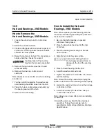
1 Remove the top drive chassis cover.
2 Remove the yoke and hub assembly. Refer to
Repair Procedure,
How to Remove the Yoke
and Hub.
3 Remove the steering cylinder. Refer to Repair
Procedure,
How to Remove a Steering
Cylinder.
4 Remove the axle cover retaining fasteners
located above the axle. Remove the chassis
cover from the machine.
5 Remove the upper wear pad retainer plate
retaining fasteners. Remove the plate from the
machine.
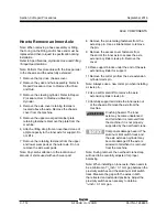
6 Attach a lifting strap from an overhead crane of
ample capacity to the inner axle for support. Do
not lift it.
7 Remove the retaining fasteners from the upper
and lower wear pads at the outer axle. Do not
remove the side wear pads.
Note: Pay careful attention to the location and
amount of shims used with each wear pad.
8 Remove the pin retaining fasteners from the
axle stop pin. Use a slide hammer to remove
the pin.
9 Remove the access cover fasteners from
the end of the inner axle to access the axle
extension cylinder clevis pin. Remove the
cover.
10 Place support blocks under the end of the axle
extension cylinder for support.
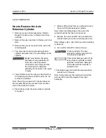
11 Remove the cotter pin from the axle extension
cylinder clevis pin.
Note: Alwayse use a new cotter pin when installing
a clevis pin.
12 Use a soft metal drift to remove the axle
extension cylinder clevis pin.
13 Carefully support and slide the inner axle out
of the chassis. Remove the axle from the
machine.
Crushing hazard. The inner
axle may become unbalanced
and fall when it is removed from
the machine if it is not properly
supported by the overhead crane.
Component damage hazard. The
aluminum limit switch track and
the axle extension cylinder may
become damaged if the axle is
allowed to fall when it is removed
from the machine.
Note: During removal, the overhead crane strap
will need to be carefully adjusted for proper
balancing.
Note: When installing an inner axle, there needs to
be a minimum of
1
/
8
inch / 3.1 mm gap between the
proximity switches and the aluminum limit switch
track. Measure the gap with the axles in both
the retracted and extended positions. Adjust the
proximity switches as necesary to obtain a
1
/
8
inch / 3.1 mm gap.
AXLE COMPONENTS
Summary of Contents for Genie S-100HD
Page 14: ...September 2016 S 100HD S 120HD Part No 1268495 xiv This page intentionally left blank ...
Page 124: ...3 94 S 100HD S 120HD Part No 1268495 September 2016 Section 3 Repair Procedures MANIFOLDS ...
Page 126: ...3 96 S 100HD S 120HD Part No 1268495 September 2016 Section 3 Repair Procedures MANIFOLDS ...
Page 201: ...Section 5 Schematics September 2016 5 19 Electrical Schematic View 1 S 100HD Models 5 20 ...
Page 204: ...September 2016 Section 5 Schematics 5 22 Electrical Schematic View 2 S 100HD Models 5 21 ...
Page 205: ...Section 5 Schematics September 2016 5 23 Electrical Schematic View 3 S 100HD Models 5 24 ...
Page 208: ...September 2016 Section 5 Schematics 5 26 Electrical Schematic View4 S 100HD Models 5 25 ...
Page 209: ...Section 5 Schematics September 2016 5 27 Electrical Schematic View 5 S 100HD Models 5 28 ...
Page 212: ...September 2016 Section 5 Schematics 5 30 Electrical Schematic View 6 S 100HD Models 5 29 ...
Page 213: ...Section 5 Schematics September 2016 5 31 Electrical Schematic View 7 S 100HD Models 5 32 ...
Page 216: ...September 2016 Section 5 Schematics 5 34 5 33 Safety Circuit Schematic S 100HD Models ...
Page 217: ...Section 5 Schematics September 2016 5 35 5 36 Electrical Schematic View 1 S 120HD Models ...
Page 220: ...September 2016 Section 5 Schematics 5 38 Electrical Schematic View 2 S 120HD Models 5 37 ...
Page 221: ...Section 5 Schematics September 2016 5 39 Electrical Schematic View 3 S 120HD Models 5 40 ...
Page 224: ...September 2016 Section 5 Schematics 5 42 Electrical Schematic View 4 S 120HD Models 5 41 ...
Page 225: ...Section 5 Schematics September 2016 5 43 Electrical Schematic View 5 S 120HD Models 5 44 ...
Page 228: ...September 2016 Section 5 Schematics 5 46 Electrical Schematic View 6 S 120HD Models 5 45 ...
Page 229: ...Section 5 Schematics September 2016 5 47 5 48 Electrical Schematic View 7 S 120HD Models ...
Page 232: ...September 2016 Section 5 Schematics 5 50 Safety Circuit Schematic S 120HD Models 5 49 ...
Page 233: ...Section 5 Schematics September 2016 5 51 Perkins 854F 34T Engine Electrical Schematic 5 52 ...
Page 235: ...Section 5 Schematics September 2016 Part No 1268495 S 100HD S 120HD 5 53 ...
Page 236: ...September 2016 Section 5 Schematics 5 54 Perkins 854F 34T Engine Electrical Harness 5 53 ...
Page 237: ...Section 5 Schematics September 2016 5 55 Deutz TD2 9 Engine Electrical Schematic 5 56 ...
Page 240: ...September 2016 Section 5 Schematics 5 58 Deutz TD2 9 Engine Electrical Harness 5 57 ...
Page 241: ...Section 5 Schematics September 2016 5 59 Hydraulic Schematic S 100HD Models 5 60 ...
Page 248: ...September 2016 Section 5 Schematics 5 66 Hydraulic Schematic S 120HD Models 5 60 ...
Page 249: ......

