Section 5 • Schematics
September 2016
1
2
3
4
5
6
7
8
N M L K J I H G F E D C B A
Part No. 1268495
S-100HD • S-120HD
5 - 21
Electrical Schematic, View 2
S-100HD Models
PCON GND
PCON PWR
P7
CAN SHIELD
RS232_RXD
RS232_TXD
BOOT
OUT PWR ENBL
HRN RLY CNTRL
CAN+
CAN-
RS232_GND
PWR-PCON ESTOP
J1
BLACK
23
PI
N
J2
WHITE
23
PI
N
P22
J3
10PI
N
P1
MEMBRANE/LED
INTERF
ACE
CARD
J1
10PIN
P1
P1
P1
P1
P1
P1
START ASSIST
AC GENERATOR
AUXILIARY
HORN
START
J2
10PI
N
P1
P1
P1
P2
P2
P2
P2
P2
P2
ENGINE SPEED
AXLE RETRACT
DRIVE ENABLE
1
SPARE 1
CRAB STEER
FRONT STEER
DRIVE SPEED
REAR STEER
AXLE EXTEND
4
2
3
5
6
PCON
MEMBRANE
P
ANEL
P2
P2
P2
P2
FUEL TYPE
COORD STEER
7
8
10
9
SPARE 2
P1-01
P1-02
P1-03
P1-04
P1-05
P1-06
P1-07
P1-08
P1-09
P1-11
P1-10
P1-12
P1-13
P1-14
P1-15
P1-20
P1-16
P1-17
P1-18
P1-19
P1-22
P1-21
P1-23
P52PCON-WH
GNDPCON-BR
P56PRV-RD
S56PRV-RD/WH
C47OUT-WH/BK
P23PCON-BK
D81CAN- -YL
-GR
C46HN-WH
5
87a
87
1
2
86
30
4
85
3
5
87a
87
1
2
86
30
4
85
3
P6R
P7R
P1-23
P1-21
P1-22
P1-19
P1-18
P1-17
P1-16
P1-20
P1-15
P1-14
P1-13
P1-12
P1-10
P1-11
P1-09
P1-08
P1-07
P1-06
P1-05
P1-04
P1-03
P1-02
P1-01
P87PTS-RD
SAFE PL TILT PWR
SAFE PL TILT GND
PTSRET-BR
PL TILT SNSR PWR
P85PTS-GN
PL TILT SNSR
C84TAY-GN/BK
PL TILT SNSR GND
PLATRET-BR
FOOT SW RTN
C56PTS-RD
FOOT SW PWR
R56PTS-RD
SAFE PL TILT OUT
C88PTS-RD/BK
LOAD SNSR PWR
LOAD SNSR OUT
LOAD SNSR GND
PROX KILL CMD
C90PXS-RD/BK
PROX KILL GND
R90PXS-RD/BK
C15PLD-OR/BK
C14PLU-OR
PROP VLV2_A
ON/OFF VLV3_B
C18PRR-GR/BK
ON/OFF VLV3_A
C17PRL-GR
VLV RTN
VLVRET-BR
PROP VLV2_B
PROP VLV1_A
PROP VLV1_B
PLAT ROT CCW
PLAT LEVEL DN
PLAT LEVEL UP
PLAT ROT CW
3
1
4
2
PROX.
SWITCH
(OPTION)
2
1
FOOTSWITCH
U20
9
10
7
6
5
4
8
3
2
1
3
2
1
6
5
4
9
8
7
10
BOOM
HARN
PCON
MANIFOLD
GR/YL
OR
BK
PLATFORM
TILT SENSOR
ASSEMBLY
6
P33-PCON
MANIFOLD
J31-TIL
TS
NS
R
4
3
2
1
5
FUSE
5 A
K1
K2
P23PCON-BK
P52PCON-WH
GNDPCON-BR
C46HN-WH
P56PR
V-
RD
S56PR
V-
RD/WH
C47OUT
-WH/BK
-Y
L
D81CAN-
-G
R
D81CAN-
-G
R
-YL
P57PBD-RD/WH
P21DCON-RD
C60AXEX-GR/WH
P53LS-WH/BK
P63LS-OR/RD
GNDDCON-BR
S56PR
V-
RD
C61AXR
T-
GR
OUT
PWR
ENABLE
PWR-PCON
EST
OP
PCON
1. PLAT SENSOR GND
2. TILT SENSOR SIG OUT
3. TILT SENSOR PWR
4. TILT SWITCH GND
5. PWR TO TILT SWITCH
6. OUT FROM TILT SWITCH
LOAD
SENSOR
ASSEMBL
Y
OPTION
3
GR
J8
J7
2
4
3
6
5
2
BL
YL
BR
OR
RD
1
BK
WH
1
2
6
5
4
3
2
1
P7-LIMI
TS
W
HARN
1
P8-LIMI
TS
W
HARN
P6R1
DCON
PWR
DCON
GND
P18
P1
1
P12
P9A
P7
R
WH
BK
2
2
1
P18
1
GR
YL
BL
6
6
5
4
4
5
P17
OR
BR
RD
22
3
3
1
1
C
C
CAN
SHIELD
BB
A
P16
A
YEL
GR
CAN
HIGH
CAN
LOW
C
C
B
A
B
A
YEL
GR
-Y
L
D81CAN-
-GR
P63LS-OR/RD
P53LS-WH/BK
C60AXEX-GR/WH
P57PBD-RD/WH
P21DCON-RD
GNDDCON-BR
S56PR
V
-RD
C61AXR
T
-GR
P6-BOOM
HARN
J6
(SLIP
RING)
(SLIP
RING)
88
88
88
88
88
88
88
88
88
88
88
1
Genie
S3800
Electrical
Schematic
ES0513
Re
vA
GR/YL
OR
RD
BK
WH
1
2
J157-BOOM
HARN
P157-PCON
J2
HARN
S132LDS-BL/WH
+
-
+
-
+
-
SAFETY CUTOUT
10 DEG
SAFETY CUTOUT
10 DEG
PLAT TILT SNSR
0-20 DEG Y AXIS
Summary of Contents for Genie S-100HD
Page 14: ...September 2016 S 100HD S 120HD Part No 1268495 xiv This page intentionally left blank ...
Page 124: ...3 94 S 100HD S 120HD Part No 1268495 September 2016 Section 3 Repair Procedures MANIFOLDS ...
Page 126: ...3 96 S 100HD S 120HD Part No 1268495 September 2016 Section 3 Repair Procedures MANIFOLDS ...
Page 201: ...Section 5 Schematics September 2016 5 19 Electrical Schematic View 1 S 100HD Models 5 20 ...
Page 204: ...September 2016 Section 5 Schematics 5 22 Electrical Schematic View 2 S 100HD Models 5 21 ...
Page 205: ...Section 5 Schematics September 2016 5 23 Electrical Schematic View 3 S 100HD Models 5 24 ...
Page 208: ...September 2016 Section 5 Schematics 5 26 Electrical Schematic View4 S 100HD Models 5 25 ...
Page 209: ...Section 5 Schematics September 2016 5 27 Electrical Schematic View 5 S 100HD Models 5 28 ...
Page 212: ...September 2016 Section 5 Schematics 5 30 Electrical Schematic View 6 S 100HD Models 5 29 ...
Page 213: ...Section 5 Schematics September 2016 5 31 Electrical Schematic View 7 S 100HD Models 5 32 ...
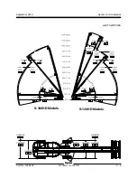
Page 216: ...September 2016 Section 5 Schematics 5 34 5 33 Safety Circuit Schematic S 100HD Models ...
Page 217: ...Section 5 Schematics September 2016 5 35 5 36 Electrical Schematic View 1 S 120HD Models ...
Page 220: ...September 2016 Section 5 Schematics 5 38 Electrical Schematic View 2 S 120HD Models 5 37 ...
Page 221: ...Section 5 Schematics September 2016 5 39 Electrical Schematic View 3 S 120HD Models 5 40 ...
Page 224: ...September 2016 Section 5 Schematics 5 42 Electrical Schematic View 4 S 120HD Models 5 41 ...
Page 225: ...Section 5 Schematics September 2016 5 43 Electrical Schematic View 5 S 120HD Models 5 44 ...
Page 228: ...September 2016 Section 5 Schematics 5 46 Electrical Schematic View 6 S 120HD Models 5 45 ...
Page 229: ...Section 5 Schematics September 2016 5 47 5 48 Electrical Schematic View 7 S 120HD Models ...
Page 232: ...September 2016 Section 5 Schematics 5 50 Safety Circuit Schematic S 120HD Models 5 49 ...
Page 233: ...Section 5 Schematics September 2016 5 51 Perkins 854F 34T Engine Electrical Schematic 5 52 ...
Page 235: ...Section 5 Schematics September 2016 Part No 1268495 S 100HD S 120HD 5 53 ...
Page 236: ...September 2016 Section 5 Schematics 5 54 Perkins 854F 34T Engine Electrical Harness 5 53 ...
Page 237: ...Section 5 Schematics September 2016 5 55 Deutz TD2 9 Engine Electrical Schematic 5 56 ...
Page 240: ...September 2016 Section 5 Schematics 5 58 Deutz TD2 9 Engine Electrical Harness 5 57 ...
Page 241: ...Section 5 Schematics September 2016 5 59 Hydraulic Schematic S 100HD Models 5 60 ...
Page 248: ...September 2016 Section 5 Schematics 5 66 Hydraulic Schematic S 120HD Models 5 60 ...
Page 249: ......

