Part No. 1268495
S-100HD • S-120HD
3 - 13
September 2016
Section 3 • Repair Procedures
How to Reset a Proportional
Valve Coil Default
(software version 2.00 and above)
Note: Software version 2.00 requires the use of
Web GPI to perform this procedure.
Refer to Diagnostic Codes
, Web GPI
.
Note: This procedure only needs to be performed
if a proportional valve has been replaced.
Note: After the valve coil defaults have been set,
each machine function threshold and default
function speed must be set. Refer to Repair
Procedure,
How to Set the Function Thresholds
and Default Function Speeds.
1 Open Web GPI and connect to the TCON.
2 Select the valve screen of the proportional
valve you want to reset.
Note: Choices are: Propel (drive) valve reset;
Boom up/down valve reset; Boom extend/retract
valve reset; or TT rotate valve reset.
3 Press "set Defaults" and enter the level
2 password (obtained from field service
personnel).
4 Enter "0" (zero) into the threshold boxes.
5 Press "send" and enter the level 2 password
(obtained from field service personnel).
6 Disconnect from the TCON and proceed with
calibration.
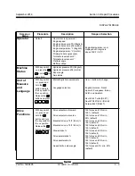
Turntable rotate functions:
Note: If the calibration fault is already displayed at
the ground box begin with step 6.
1 Turn the key switch to the off position. Confirm
the red Emergency Stop button at the platform
and ground controls is in the on position.
2 Press and hold the enter button
on the
ground control panel while turning the key
switch to platform controls. Hold the enter
button for approximately 5 seconds.
3 Press the minus button
twice, then press the
enter button
twice.
4 Use the scroll button to scroll through the
menu until
reset
turntable
rotate
joystick
defaults
is displayed. Press the
button to
select
yes
, then press the
button.
5 Exit programming mode.
Note: To exit programming mode, use the scroll
button to scroll through the menu until the
screen displays exit, then press the plus button
once, change the NO to YES, and press the enter
button
.
6 Do not start the engine.
7 Locate the primary boom/turntable rotate
joystick.
8 Move the boom/turntable joystick full stroke in
the left direction and hold for 5 seconds, then
return to the center or neutral position.
9 Move the boom/turntable joystick full stroke in
the right direction and hold for 5 seconds, then
return to the center or neutral position.
Result: The alarm at the ground controls should
sound for a successful calibration.
Result: If the alarm does not sound, repeat the
calibration procedure, beginning with step 1.
PLATFORM CONTROLS
Summary of Contents for Genie S-100HD
Page 14: ...September 2016 S 100HD S 120HD Part No 1268495 xiv This page intentionally left blank ...
Page 124: ...3 94 S 100HD S 120HD Part No 1268495 September 2016 Section 3 Repair Procedures MANIFOLDS ...
Page 126: ...3 96 S 100HD S 120HD Part No 1268495 September 2016 Section 3 Repair Procedures MANIFOLDS ...
Page 201: ...Section 5 Schematics September 2016 5 19 Electrical Schematic View 1 S 100HD Models 5 20 ...
Page 204: ...September 2016 Section 5 Schematics 5 22 Electrical Schematic View 2 S 100HD Models 5 21 ...
Page 205: ...Section 5 Schematics September 2016 5 23 Electrical Schematic View 3 S 100HD Models 5 24 ...
Page 208: ...September 2016 Section 5 Schematics 5 26 Electrical Schematic View4 S 100HD Models 5 25 ...
Page 209: ...Section 5 Schematics September 2016 5 27 Electrical Schematic View 5 S 100HD Models 5 28 ...
Page 212: ...September 2016 Section 5 Schematics 5 30 Electrical Schematic View 6 S 100HD Models 5 29 ...
Page 213: ...Section 5 Schematics September 2016 5 31 Electrical Schematic View 7 S 100HD Models 5 32 ...
Page 216: ...September 2016 Section 5 Schematics 5 34 5 33 Safety Circuit Schematic S 100HD Models ...
Page 217: ...Section 5 Schematics September 2016 5 35 5 36 Electrical Schematic View 1 S 120HD Models ...
Page 220: ...September 2016 Section 5 Schematics 5 38 Electrical Schematic View 2 S 120HD Models 5 37 ...
Page 221: ...Section 5 Schematics September 2016 5 39 Electrical Schematic View 3 S 120HD Models 5 40 ...
Page 224: ...September 2016 Section 5 Schematics 5 42 Electrical Schematic View 4 S 120HD Models 5 41 ...
Page 225: ...Section 5 Schematics September 2016 5 43 Electrical Schematic View 5 S 120HD Models 5 44 ...
Page 228: ...September 2016 Section 5 Schematics 5 46 Electrical Schematic View 6 S 120HD Models 5 45 ...
Page 229: ...Section 5 Schematics September 2016 5 47 5 48 Electrical Schematic View 7 S 120HD Models ...
Page 232: ...September 2016 Section 5 Schematics 5 50 Safety Circuit Schematic S 120HD Models 5 49 ...
Page 233: ...Section 5 Schematics September 2016 5 51 Perkins 854F 34T Engine Electrical Schematic 5 52 ...
Page 235: ...Section 5 Schematics September 2016 Part No 1268495 S 100HD S 120HD 5 53 ...
Page 236: ...September 2016 Section 5 Schematics 5 54 Perkins 854F 34T Engine Electrical Harness 5 53 ...
Page 237: ...Section 5 Schematics September 2016 5 55 Deutz TD2 9 Engine Electrical Schematic 5 56 ...
Page 240: ...September 2016 Section 5 Schematics 5 58 Deutz TD2 9 Engine Electrical Harness 5 57 ...
Page 241: ...Section 5 Schematics September 2016 5 59 Hydraulic Schematic S 100HD Models 5 60 ...
Page 248: ...September 2016 Section 5 Schematics 5 66 Hydraulic Schematic S 120HD Models 5 60 ...
Page 249: ......

