3 - 26
S-100HD • S-120HD
Part No. 1268495
September 2016
Section 3 • Repair Procedures
BOOM COMPONENTS
4-1
Cable Track
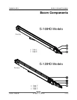
The cable track and boom cable tube guides
cables and hoses running up the boom. The
cable track can be repaired link by link without
removing the cables and hoses that run through
it. Removing the entire cable track assembly may
be necessary when performing major repairs that
involve removing the boom.
How to Remove the Boom
Cable Track Assembly
Note: When removing a hose assembly or fitting,
the O-ring on the fitting and/or hose end must be
replaced and then torqued to specification during
installation.
Refer to Specifications,
Hydraulic Hose and Fitting
Torque Specifications.
Note: Perform this procedure with the boom
horizontal.
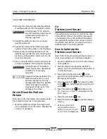
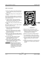
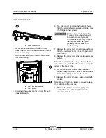
1 Remove the protective cover from the platform
manifold.
2 Remove the cable track assembly end covers
from both the pivot and platform end of the
machine.
For S-100HD machines proceed to step 4.
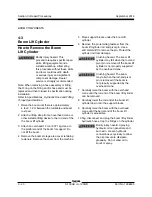
3 Using an appropriate overhead lifting device
and beginning at the pivot end, remove the
cable track covers from the number 0 boom
tube.
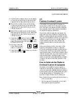
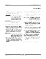
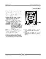
4 Tag, disconnect and plug the two hydraulic
hoses from the boom pull tube to the platform
manifold. Secure them to the cable track
assembly.
Bodily injury hazard. Spraying
hydraulic oil can penetrate and
burn skin. Loosen hydraulic
connections very slowly to allow
the oil pressure to dissipate
gradually. Do not allow oil to
squirt or spray.
5 Tag and disconnect the electrical connectors
from the bottom of the control box.
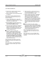
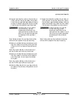
6 Remove the fasteners holding the pull tube to
the number 3 boom tube.
7 Remove the fasteners holding the pull tube to
the number 2 boom tube.
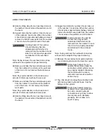
8 Tag and disconnect the electrical cables located
at the platform end of the main cable track
tube on the engine side of the machine. These
cables include platform controls, limit and
proximity switches and work light (if installed).
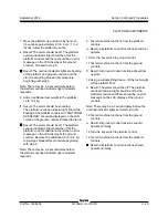
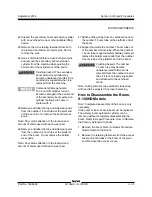
9 Tag, disconnect and plug the platform manifold
hydraulic hoses from the bulkhead at the
platform end of the main cable track tube on
the engine side of the machine. Cap the fittings.
Bodily injury hazard. Spraying
hydraulic oil can penetrate and
burn skin. Loosen hydraulic
connections very slowly to allow
the oil pressure to dissipate
gradually. Do not allow oil to
squirt or spray.
Summary of Contents for Genie S-100HD
Page 14: ...September 2016 S 100HD S 120HD Part No 1268495 xiv This page intentionally left blank ...
Page 124: ...3 94 S 100HD S 120HD Part No 1268495 September 2016 Section 3 Repair Procedures MANIFOLDS ...
Page 126: ...3 96 S 100HD S 120HD Part No 1268495 September 2016 Section 3 Repair Procedures MANIFOLDS ...
Page 201: ...Section 5 Schematics September 2016 5 19 Electrical Schematic View 1 S 100HD Models 5 20 ...
Page 204: ...September 2016 Section 5 Schematics 5 22 Electrical Schematic View 2 S 100HD Models 5 21 ...
Page 205: ...Section 5 Schematics September 2016 5 23 Electrical Schematic View 3 S 100HD Models 5 24 ...
Page 208: ...September 2016 Section 5 Schematics 5 26 Electrical Schematic View4 S 100HD Models 5 25 ...
Page 209: ...Section 5 Schematics September 2016 5 27 Electrical Schematic View 5 S 100HD Models 5 28 ...
Page 212: ...September 2016 Section 5 Schematics 5 30 Electrical Schematic View 6 S 100HD Models 5 29 ...
Page 213: ...Section 5 Schematics September 2016 5 31 Electrical Schematic View 7 S 100HD Models 5 32 ...
Page 216: ...September 2016 Section 5 Schematics 5 34 5 33 Safety Circuit Schematic S 100HD Models ...
Page 217: ...Section 5 Schematics September 2016 5 35 5 36 Electrical Schematic View 1 S 120HD Models ...
Page 220: ...September 2016 Section 5 Schematics 5 38 Electrical Schematic View 2 S 120HD Models 5 37 ...
Page 221: ...Section 5 Schematics September 2016 5 39 Electrical Schematic View 3 S 120HD Models 5 40 ...
Page 224: ...September 2016 Section 5 Schematics 5 42 Electrical Schematic View 4 S 120HD Models 5 41 ...
Page 225: ...Section 5 Schematics September 2016 5 43 Electrical Schematic View 5 S 120HD Models 5 44 ...
Page 228: ...September 2016 Section 5 Schematics 5 46 Electrical Schematic View 6 S 120HD Models 5 45 ...
Page 229: ...Section 5 Schematics September 2016 5 47 5 48 Electrical Schematic View 7 S 120HD Models ...
Page 232: ...September 2016 Section 5 Schematics 5 50 Safety Circuit Schematic S 120HD Models 5 49 ...
Page 233: ...Section 5 Schematics September 2016 5 51 Perkins 854F 34T Engine Electrical Schematic 5 52 ...
Page 235: ...Section 5 Schematics September 2016 Part No 1268495 S 100HD S 120HD 5 53 ...
Page 236: ...September 2016 Section 5 Schematics 5 54 Perkins 854F 34T Engine Electrical Harness 5 53 ...
Page 237: ...Section 5 Schematics September 2016 5 55 Deutz TD2 9 Engine Electrical Schematic 5 56 ...
Page 240: ...September 2016 Section 5 Schematics 5 58 Deutz TD2 9 Engine Electrical Harness 5 57 ...
Page 241: ...Section 5 Schematics September 2016 5 59 Hydraulic Schematic S 100HD Models 5 60 ...
Page 248: ...September 2016 Section 5 Schematics 5 66 Hydraulic Schematic S 120HD Models 5 60 ...
Page 249: ......

