Part No. 1268495
S-100HD • S-120HD
3 - 69
September 2016
Section 3 • Repair Procedures
9-3
Auxiliary Pump
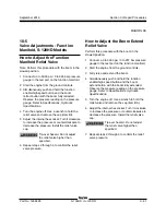
How to Test the Auxiliary Pump
The auxiliary pump is a 2-section, gear-type pump.
Pump number 1 is the pump section closest to
the pump motor and pump number 2 is the pump
section that is farther from the pump motor. Each
section of the pump has its own relief valve located
within the pump body.
Note: When removing a hose assembly or fitting,
the O-ring on the fitting and/or hose end must be
replaced and then torqued to specification during
installation. Refer to Specifications,
Hydraulic
Hose and Fitting Torque Specifications.
1 Disconnect and plug the high pressure
hydraulic hose from pump number 1.
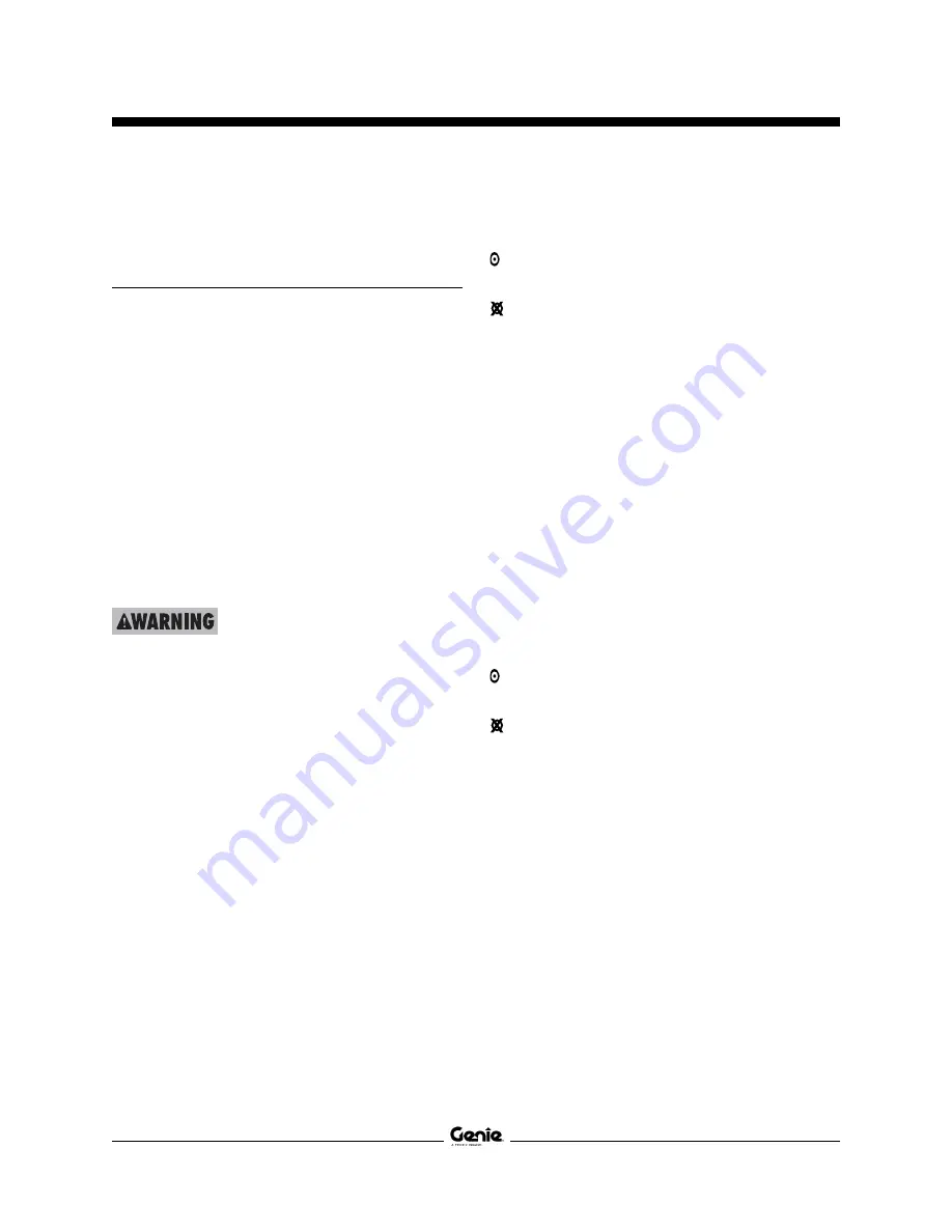
Bodily injury hazard. Spraying
hydraulic oil can penetrate and
burn skin. Loosen hydraulic
connections very slowly to allow
the oil pressure to dissipate
gradually. Do not allow oil to squirt
or spray.
2 Connect a 0 to 5000 psi / 0 to 345 bar pressure
gauge to the high pressure port on pump
number 1.
3 Turn the key switch to ground control and
pull out the Emergency Stop button to the
on
position.
4 Activate any function using auxiliary power.
Result: If the pressure gauge reads 2500 psi /
172 bar, immediately stop. The pump is good.
Result: If pressure fails to reach 2500 psi
/ 172 bar, the internal relief valve setting is
incorrect or the pump is bad and will need to be
serviced or replaced.
5 Turn the key switch to the
off
position.
6 Remove the pressure gauge and reconnect the
hydraulic hose.
7 Disconnect the hydraulic hose from the high
pressure port from pump number 2.
8 Connect a 0 to 5000 psi / 0 to 345 bar pressure
gauge to the high pressure port on pump
number 2.
9 Turn the key switch to ground control and
pull out the Emergency Stop button to the
on
position.
10 Activate any function using auxiliary power.
Result: If the pressure gauge reads 3000 psi /
207 bar, immediately stop. The pump is good.
Result: If pressure fails to reach 3000 psi
/ 207 bar, the internal relief valve setting is
incorrect or the pump is bad and will need to be
serviced or replaced.
11 Remove the pressure gauge and reconnect the
hydraulic hose.
How to Remove the Auxiliary
Pump
1 Open the ground controls side turntable cover.
2 Tag, disconnect and plug the hydraulic hoses
from the pumps.
3 Remove the pump mounting fasteners and
remove the pump from the pump motor.
HYDRAULIC PUMPS
Summary of Contents for Genie S-100HD
Page 14: ...September 2016 S 100HD S 120HD Part No 1268495 xiv This page intentionally left blank ...
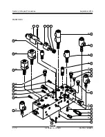
Page 124: ...3 94 S 100HD S 120HD Part No 1268495 September 2016 Section 3 Repair Procedures MANIFOLDS ...
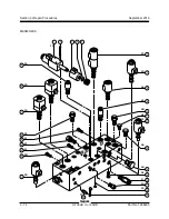
Page 126: ...3 96 S 100HD S 120HD Part No 1268495 September 2016 Section 3 Repair Procedures MANIFOLDS ...
Page 201: ...Section 5 Schematics September 2016 5 19 Electrical Schematic View 1 S 100HD Models 5 20 ...
Page 204: ...September 2016 Section 5 Schematics 5 22 Electrical Schematic View 2 S 100HD Models 5 21 ...
Page 205: ...Section 5 Schematics September 2016 5 23 Electrical Schematic View 3 S 100HD Models 5 24 ...
Page 208: ...September 2016 Section 5 Schematics 5 26 Electrical Schematic View4 S 100HD Models 5 25 ...
Page 209: ...Section 5 Schematics September 2016 5 27 Electrical Schematic View 5 S 100HD Models 5 28 ...
Page 212: ...September 2016 Section 5 Schematics 5 30 Electrical Schematic View 6 S 100HD Models 5 29 ...
Page 213: ...Section 5 Schematics September 2016 5 31 Electrical Schematic View 7 S 100HD Models 5 32 ...
Page 216: ...September 2016 Section 5 Schematics 5 34 5 33 Safety Circuit Schematic S 100HD Models ...
Page 217: ...Section 5 Schematics September 2016 5 35 5 36 Electrical Schematic View 1 S 120HD Models ...
Page 220: ...September 2016 Section 5 Schematics 5 38 Electrical Schematic View 2 S 120HD Models 5 37 ...
Page 221: ...Section 5 Schematics September 2016 5 39 Electrical Schematic View 3 S 120HD Models 5 40 ...
Page 224: ...September 2016 Section 5 Schematics 5 42 Electrical Schematic View 4 S 120HD Models 5 41 ...
Page 225: ...Section 5 Schematics September 2016 5 43 Electrical Schematic View 5 S 120HD Models 5 44 ...
Page 228: ...September 2016 Section 5 Schematics 5 46 Electrical Schematic View 6 S 120HD Models 5 45 ...
Page 229: ...Section 5 Schematics September 2016 5 47 5 48 Electrical Schematic View 7 S 120HD Models ...
Page 232: ...September 2016 Section 5 Schematics 5 50 Safety Circuit Schematic S 120HD Models 5 49 ...
Page 233: ...Section 5 Schematics September 2016 5 51 Perkins 854F 34T Engine Electrical Schematic 5 52 ...
Page 235: ...Section 5 Schematics September 2016 Part No 1268495 S 100HD S 120HD 5 53 ...
Page 236: ...September 2016 Section 5 Schematics 5 54 Perkins 854F 34T Engine Electrical Harness 5 53 ...
Page 237: ...Section 5 Schematics September 2016 5 55 Deutz TD2 9 Engine Electrical Schematic 5 56 ...
Page 240: ...September 2016 Section 5 Schematics 5 58 Deutz TD2 9 Engine Electrical Harness 5 57 ...
Page 241: ...Section 5 Schematics September 2016 5 59 Hydraulic Schematic S 100HD Models 5 60 ...
Page 248: ...September 2016 Section 5 Schematics 5 66 Hydraulic Schematic S 120HD Models 5 60 ...
Page 249: ......

