Service and Repair Manual
December 2019
Axle Components
124
SX
™
-150
Part No. 1300669GT
How to C alibr ate a R epl acem ent Steer Sensor
How to Calibrate a Replacement
Steer Sensor
Note: If a steer angle sensor has been removed or
replaced, the steer angle sensors will need to be
calibrated.
Note: Perform this procedure with the axles
retracted and the tires straightened.
Note: Two people will be required to perform this
procedure.
Note: Be sure the yoke pivot pin retaining plate is
fully engaged into the pivot pin and that the
fasteners are securely tightened.
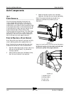
1 Start the engine from the platform controls.
2 Select the proper steer mode. If a front
(square-end) steer angle sensor has been
replaced, select rear steer mode. If a rear
(circle-end) steer angle sensor has been
replaced, select front steer mode.
3 Have another person press down the foot
switch.
4 At the new steer angle sensor, loosen the
steer angle sensor cover retaining fasteners.
Do not remove the fasteners or the sensor
cover.
5 Rotate the sensor cover clockwise or
counterclockwise until the tire is straight in
relation with the other tires. Tighten the sensor
cover fasteners.
Note: If available, WebGPI can also be used for
this procedure.
6 Push in the red Emergency Stop button to the
off position.
How to C alibr ate All Steer Sensors
How to Calibrate All Steer
Sensors
Note: This procedure will only need to be
performed if the ground controls circuit board
(TCON) has been replaced.
Note: Perform this procedure with the axles
retracted and the tires straightened.
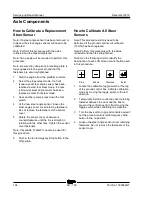
Note: Use the following chart to identify the
description of each LCD screen control button used
in this procedure.
Plus
Minus
Previous
Enter
1 Locate the calibration toggle switch at the top
of the ground control box. Activate calibration
mode by moving the toggle switch in the left
direction.
2 Temporarily install a control box door retaining
fastener between the door and the box to
prevent the control box door from moving the
toggle switch while calibrating the machine.
3 Turn the key switch to ground controls and pull
out the ground controls red Emergency Stop
button to the on position.
4 Loosen the steer angle sensor cover retaining
fasteners. Do not remove the fasteners or the
sensor cover.
Summary of Contents for Genie SX-150
Page 105: ...December 2019 Service and Repair Manual Manifolds Part No 1300669GT SX 150 93 ...
Page 107: ...December 2019 Service and Repair Manual Manifolds Part No 1300669GT SX 150 95 ...
Page 109: ...December 2019 Service and Repair Manual Manifolds Part No 1300669GT SX 150 97 ...
Page 117: ...December 2019 Service and Repair Manual Part No 1300669GT SX 150 105 ...
Page 119: ...December 2019 Service and Repair Manual Part No 1300669GT SX 150 107 ...
Page 122: ...Service and Repair Manual December 2019 Manifolds 110 SX 150 Part No 1300669GT ...
Page 124: ...Service and Repair Manual December 2019 Manifolds 112 SX 150 Part No 1300669GT ...
Page 229: ...December 2019 Service and Repair Manual 217 Control Circuits Horn ...
Page 230: ...Service and Repair Manual December 2019 218 SX 150 Part No 1300669GT Control Circuits Horn ...
Page 231: ...December 2019 Service and Repair Manual Part No 1300669GT SX 150 219 Control Circuits Power ...
Page 232: ...Service and Repair Manual December 2019 220 Control Circuits Power ...
Page 233: ...December 2019 Service and Repair Manual 221 Control Circuits Can Bus ...
Page 234: ...Service and Repair Manual December 2019 222 SX 150 Part No 1300669GT Control Circuits Can Bus ...
Page 236: ...Service and Repair Manual December 2019 224 Control Circuits Deutz TD2011L04i Engine ...
Page 237: ...December 2019 Service and Repair Manual 225 Control Circuits Deutz TD 2 9 L4Engine ...
Page 240: ...Service and Repair Manual December 2019 228 Control Circuits Perkins 1104D 44T Engine ...
Page 241: ...December 2019 Service and Repair Manual 229 Control Circuits Perkins 854F 34T Engine ...
Page 244: ...Service and Repair Manual December 2019 232 Control Circuits Axle Extend Retract ...
Page 245: ...December 2019 Service and Repair Manual 233 Control Circuits Steering ...
Page 247: ...December 2019 Service and Repair Manual Part No 1300669GT SX 150 235 Control Circuits Propel ...
Page 248: ...Service and Repair Manual December 2019 236 Control Circuits Propel ...
Page 249: ...December 2019 Service and Repair Manual 237 Control Circuits Turntable Rotate ...
Page 252: ...Service and Repair Manual December 2019 240 Control Circuits Boom Up Down ...
Page 253: ...December 2019 Service and Repair Manual 241 Control Circuits Boom Extend Retract ...
Page 261: ...December 2019 Service and Repair Manual 249 Control Circuits Recovery PLD ...
Page 264: ...Service and Repair Manual December 2019 252 Control Circuits Telematics ...
Page 265: ...December 2019 Service and Repair Manual 253 Generator Receptacle Wiring ANSI CSA ...
Page 268: ...Service and Repair Manual December 2019 256 Generator Receptacle Wiring CE ...
Page 269: ...December 2019 Service and Repair Manual 257 Perkins 1104D 44T Engine Electrical Schematic ...
Page 272: ...Service and Repair Manual December 2019 260 Perkins 854F 34T Engine Electrical Schematic ...
Page 273: ...December 2019 Service and Repair Manual 261 Perkins 854F 34T Engine Harness ...
Page 276: ...Service and Repair Manual December 2019 264 Deutz TD 2 9 L4 Engine Electrical Schematic ...
Page 277: ...December 2019 Service and Repair Manual 265 Deutz TD 2 9 L4 Engine Harness ...
Page 279: ...December 2019 Service and Repair Manual 267 Hydraulic Schematic ...
Page 280: ...Service and Repair Manual December 2019 268 Hydraulic Schematic ...
Page 282: ......


