Service and Repair Manual
December 2019
Boom Components
46
SX
™
-150
Part No. 1300669GT
4-1
Primary Boom Cable Track
The primary boom cable track guides the cables
and hoses running up the boom. It can be repaired
link by link without removing the cables and hoses
that run through it. Removing the entire primary
boom cable track is only necessary when
performing major repairs that involve removing the
primary boom.
How to Remove the Primary
Boom Cable Track
Note: When removing a hose assembly or fitting,
the O-ring (if equipped) on the fitting and/or hose
end must be replaced. All connections must be
torqued to specification during installation. Refer to
Specifications,
Hydraulic Hose and Fitting Torque
Specifications.
Note: Perform this procedure with the machine on
a firm, level surface.
Note: Perform this procedure with the boom in the
stowed position.
1 Tag and disconnect the electrical connectors
from the boom #1 cable track.
2 Disconnect the AC electrical wire and option
wires and hoses.
3 Tag and disconnect the ground box
harnesses.
4 Pull the electrical cables out of the lower cable
track that lead to the primary boom.
Component damage hazard.
Cables can be damaged if they
are kinked or pinched.
5 Tag and disconnect the electrical connectors
from the jib boom manifold located at the
platform end of the primary boom.
6 Tag, disconnect and plug the two hydraulic
hoses from the side of the jib boom manifold
that lead to the primary boom cable track. Cap
the fittings on the manifold.
Bodily injury hazard. Spraying
hydraulic oil can penetrate and
burn skin. Loosen hydraulic
connections very slowly to allow
the oil pressure to dissipate
gradually. Do not allow oil to
squirt or spray.
7 Tag and disconnect the electrical connector
from the limit switches on the sides of the
primary boom. Do not remove the limit
switches.
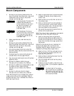
8 Remove the retaining fasteners from the cable
track guide at the platform end of the boom.
Remove the cable track guide from the
machine.
9 Disconnect the platform box harness, the AC
electrical cable and option wires and hoses
from the platform.
10 Pull the wires and hoses from the jib boom.
Summary of Contents for Genie SX-150
Page 105: ...December 2019 Service and Repair Manual Manifolds Part No 1300669GT SX 150 93 ...
Page 107: ...December 2019 Service and Repair Manual Manifolds Part No 1300669GT SX 150 95 ...
Page 109: ...December 2019 Service and Repair Manual Manifolds Part No 1300669GT SX 150 97 ...
Page 117: ...December 2019 Service and Repair Manual Part No 1300669GT SX 150 105 ...
Page 119: ...December 2019 Service and Repair Manual Part No 1300669GT SX 150 107 ...
Page 122: ...Service and Repair Manual December 2019 Manifolds 110 SX 150 Part No 1300669GT ...
Page 124: ...Service and Repair Manual December 2019 Manifolds 112 SX 150 Part No 1300669GT ...
Page 229: ...December 2019 Service and Repair Manual 217 Control Circuits Horn ...
Page 230: ...Service and Repair Manual December 2019 218 SX 150 Part No 1300669GT Control Circuits Horn ...
Page 231: ...December 2019 Service and Repair Manual Part No 1300669GT SX 150 219 Control Circuits Power ...
Page 232: ...Service and Repair Manual December 2019 220 Control Circuits Power ...
Page 233: ...December 2019 Service and Repair Manual 221 Control Circuits Can Bus ...
Page 234: ...Service and Repair Manual December 2019 222 SX 150 Part No 1300669GT Control Circuits Can Bus ...
Page 236: ...Service and Repair Manual December 2019 224 Control Circuits Deutz TD2011L04i Engine ...
Page 237: ...December 2019 Service and Repair Manual 225 Control Circuits Deutz TD 2 9 L4Engine ...
Page 240: ...Service and Repair Manual December 2019 228 Control Circuits Perkins 1104D 44T Engine ...
Page 241: ...December 2019 Service and Repair Manual 229 Control Circuits Perkins 854F 34T Engine ...
Page 244: ...Service and Repair Manual December 2019 232 Control Circuits Axle Extend Retract ...
Page 245: ...December 2019 Service and Repair Manual 233 Control Circuits Steering ...
Page 247: ...December 2019 Service and Repair Manual Part No 1300669GT SX 150 235 Control Circuits Propel ...
Page 248: ...Service and Repair Manual December 2019 236 Control Circuits Propel ...
Page 249: ...December 2019 Service and Repair Manual 237 Control Circuits Turntable Rotate ...
Page 252: ...Service and Repair Manual December 2019 240 Control Circuits Boom Up Down ...
Page 253: ...December 2019 Service and Repair Manual 241 Control Circuits Boom Extend Retract ...
Page 261: ...December 2019 Service and Repair Manual 249 Control Circuits Recovery PLD ...
Page 264: ...Service and Repair Manual December 2019 252 Control Circuits Telematics ...
Page 265: ...December 2019 Service and Repair Manual 253 Generator Receptacle Wiring ANSI CSA ...
Page 268: ...Service and Repair Manual December 2019 256 Generator Receptacle Wiring CE ...
Page 269: ...December 2019 Service and Repair Manual 257 Perkins 1104D 44T Engine Electrical Schematic ...
Page 272: ...Service and Repair Manual December 2019 260 Perkins 854F 34T Engine Electrical Schematic ...
Page 273: ...December 2019 Service and Repair Manual 261 Perkins 854F 34T Engine Harness ...
Page 276: ...Service and Repair Manual December 2019 264 Deutz TD 2 9 L4 Engine Electrical Schematic ...
Page 277: ...December 2019 Service and Repair Manual 265 Deutz TD 2 9 L4 Engine Harness ...
Page 279: ...December 2019 Service and Repair Manual 267 Hydraulic Schematic ...
Page 280: ...Service and Repair Manual December 2019 268 Hydraulic Schematic ...
Page 282: ......

