REV C
Section 4 • Repair Procedures
June 2005
Part No. 52075
TMZ-34/19
4 - 23
GROUND CONTROLS
5-4
Software Configuration
TMZ-34 models manufactured in the 1998 and
1999 model years (from serial number T3498-001
to T3499-769) were originally equipped with
ground controls boxes containing three printed
circuit boards. Machine functions are activated
using push buttons on the exterior of the box.
Beginning with the 2000 model year (from serial
number T3400-001 to date), the ground control box
was changed to a two-board configuration. The
push buttons used to activate machine functions
on earlier models were replaced with a membrane
overlay decal, mounted on the exterior of the box.
Programming for all configurations of the the 1998
and 1999 model years (from serial number
T3498-001 to T3499-769) is contained in the
EPROM, which is installed into the CPU circuit
board.
Beginning with the 2000 model year, the machine
can be configured by changing the combination of
toggles of the DIP switch mounted on the CPU
circuit board.
The following procedures will not
apply for machines manufactured
in the 1998 and 1999 model years.
How to Determine
the DIP Switch Configuration
A diagnostic display was
incorporated into the ground
controls after serial number
T3402-115. The following
procedure will not apply to
machines before serial number
T3402-116.
1 Turn the key switch to platform control and pull
out the red Emergency Stop button to the on
position at both the ground and platform
controls.
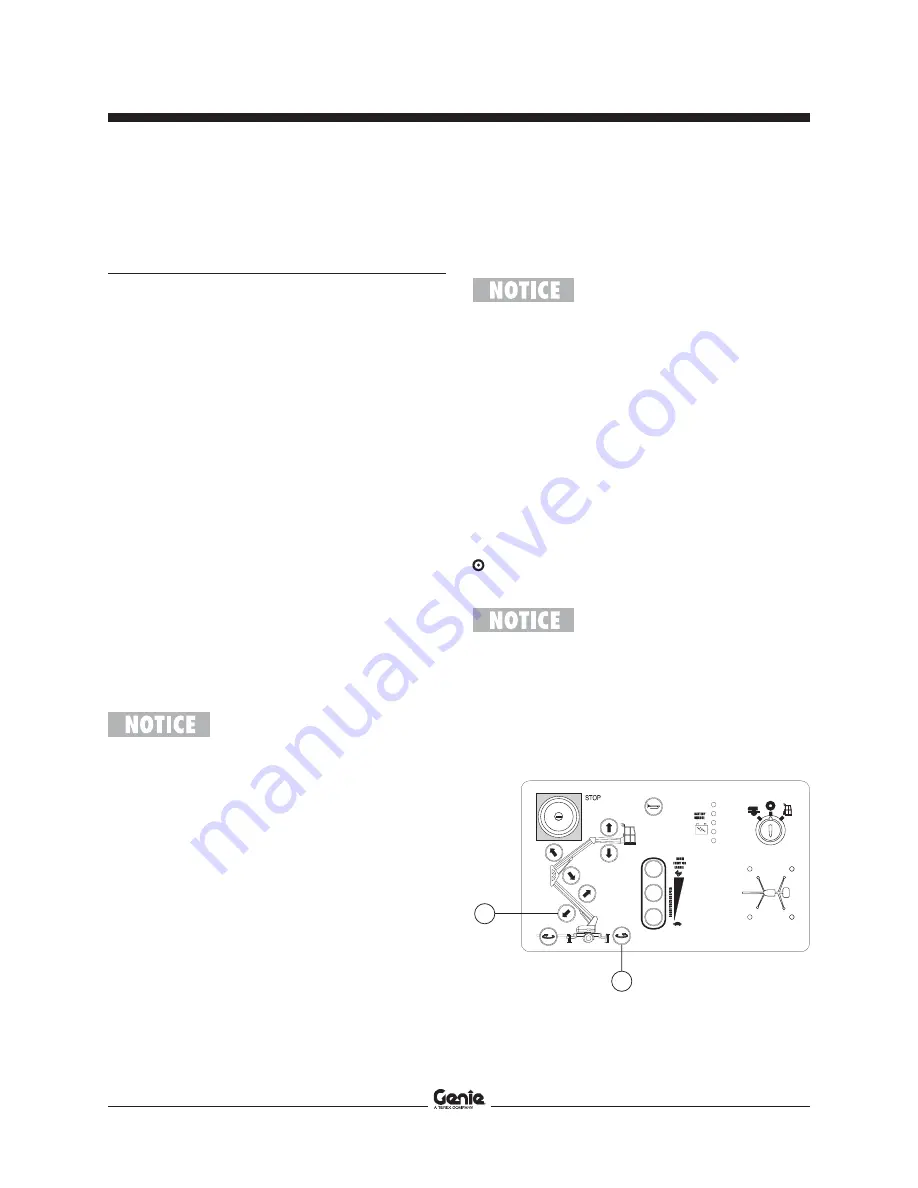
2 Press and hold both the secondary down button
and the turntable rotate counterclockwise
button at the ground controls.
Result: The DIP switch settings will appear in
the diagnostic display.
The display will show each toggle
of the DIP switch in numerical
order from 1 through 16, and
whether the toggle is in the on
position (01) or off position (00).
For example, 0401 shown in the
diagnostic display indicates that
the fourth toggle is in the on
position.
b
a
a
secondary down
b
turntable rotate counterclockwise


