REV C
Section 4 • Repair Procedures
June 2005
4 - 24
TMZ-34/19
Part No. 52075
N.C.
N.O.
N.O.
SW25
DIP SWITCH
SW25A
DIP SWITCH
D7
VOLTAGE
REGULATOR
P1
EMERGENCY
STOP
KS1
KEY
SWITCH
d
c
b
a
1
2
3
4
5
6
7
8
ON
K
J
1
2
3
4
5
6
7
8
ON
K
J
e
e
How to
Set the DIP Switch
1 Turn the key switch to the off position and push
in the red Emergency Stop button to the off
position at both the ground and platform
controls.
2 Remove the fasteners securing the top to the
ground controls box and open the ground
control box.
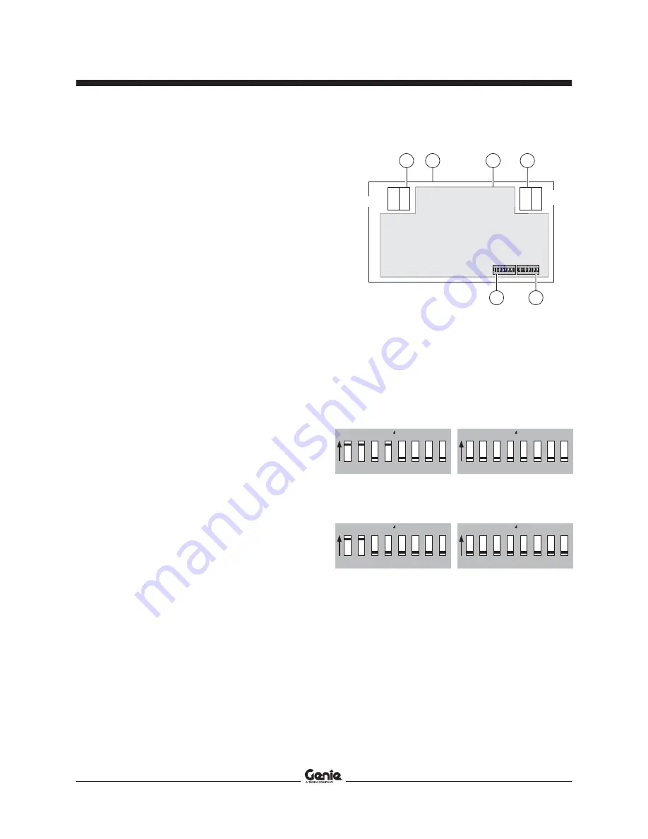
3 Rotate the top of the ground control box to the
position shown in the following illustration to
correctly identify the configuration of the DIP
switch settings.
4 Locate the DIP switch on the circuit board.
Move the DIP switch settings to correspond
with the configuration of the machine options as
illustrated below.
5 Close the lid and install the fasteners.
DIP Switch Legend
Toggle
Description
Position
1
All models
On
2
Hour meter/flashing beacon
On
3
Not used
Off
4
Outriggers
hydraulic
Off
manual
On
5 - 16
Not used
GROUND CONTROLS
1
2
3
4
5
6
7
8
ON
K
J
1
2
3
4
5
6
7
8
ON
K
J
1
2
3
4
5
6
7
8
ON
K
J
1
2
3
4
5
6
7
8
ON
K
J
a
key switch KS1
b
ground control lid
c
CPU/display circuit board U22
d
Emergency Stop P1
e
DIP switch SW25A
f
DIP switch SW25
models with manual outriggers
models with hydraulic outriggers


