October 2018
Service and Repair Manual
Ground Controls
Part No. 1268557GT
Z®-135
/70
105
6-4
Full Machine Calibration
Full machine calibration must be completed in the
proper sequence when the ALC-1000 circuit board
(TCON) in the ground control box has been
replaced or the turntable level sensor (SCON) has
been replaced.
How to Fully Calibrate the
Machine
Calibration procedures shall only be completed by
qualified technicians that have Genie factory
service training.
Tip-over hazard. Failure to
calibrate the machine in the
proper sequence could cause the
machine to tip over resulting in
death or serious injury.
Note: A digital level will be required to perform this
procedure.
Note: A kit is available through Genie Product
Support (Genie part number 58351). This kit
includes a digital level with a magnetic base and
cable harnesses.
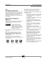
Note: Use the following chart to identify the
description of each LCD screen control button used
in this procedure.
Plus
Minus
Previous
Enter
Note: Start this procedure with the booms in the
fully stowed position and the axle retracted.
Full machine calibration must be completed in the
following sequence:
•
Select engine configuration. Refer to Repair
Section, Display Module.
Unit of Measure
and Language
.
•
Joysticks. Refer to Repair Procedure,
How
to Calibrate a Joystick
.
•
Turntable level sensor. Refer to Repair
Procedure,
How to Calibrate the Turntable
Level Sensor
.
•
Platform level sensor. Refer to Repair
Procedure,
How to Calibrate the Platform
Level Sensor
.
•
Axle angle sensors. Refer to Repair
Procedure,
How to Calibrate the Axle Angle
Sensors
.
•
Steer sensors. Refer to Repair Procedure,
How to Calibrate All Steer Sensors
.
•
Secondary boom angle sensor. Refer to
Repair Procedure,
How to Calibrate the
Secondary Boom Angle Sensor
.
•
Primary boom angle sensor. Refer to Repair
Procedure,
How to Calibrate the Primary
Boom Angle Sensor
.
•
Jib boom bellcrank angle sensor. Refer to
Repair Procedure,
How to Calibrate the Jib
Boom Bellcrank Sensor
.
•
Select option configuration. Refer to Repair
Section, Display Module.
Options
.
Summary of Contents for Genie Z-135/70
Page 14: ......
Page 37: ...October 2018 Service and Repair Manual Specifications Part No 1268557GT Z 135 70 23 T ...
Page 135: ...October 2018 Service and Repair Manual Manifolds Part No 1268557GT Z 135 70 121 ...
Page 137: ...October 2018 Service and Repair Manual Manifolds Part No 1268557GT Z 135 70 123 ...
Page 139: ...October 2018 Service and Repair Manual Manifolds Part No 1268557GT Z 135 70 125 ...
Page 141: ...October 2018 Service and Repair Manual Manifolds Part No 1268557GT Z 135 70 127 ...
Page 147: ...October 2018 Service and Repair Manual Manifolds Part No 1268557GT Z 135 70 133 ...
Page 153: ...October 2018 Service and Repair Manual Manifolds Part No 1268557GT Z 135 70 139 ...
Page 155: ...October 2018 Service and Repair Manual Manifolds Part No 1268557GT Z 135 70 141 ...
Page 159: ...October 2018 Service and Repair Manual Manifolds Part No 1268557GT Z 135 70 145 ...
Page 161: ...October 2018 Service and Repair Manual Manifolds Part No 1268557GT Z 135 70 147 ...
Page 233: ...October 2018 Service and Repair Manual 219 Generator Wiring Schematic ...
Page 236: ...Service and Repair Manual October 2018 222 Hydraulic Generator Welder Option ...
Page 242: ...Service and Repair Manual October 2018 228 Hydraulic Schematic from serial number 535 ...
Page 244: ......


