4-2
Z
®
-33/18
Part No. 1268514GT
January 2020
Section 4 • Fault Codes
At least one fault code is present when the service
icon is shown on the display.
1 Turn the key switch to platform control.
2 Pull out the red Emergency Stop button to the
on position at both the ground and platform
controls.
3 Do not press down the foot switch.
4 Move and hold the drive enable toggle switch
in the right direction and hold the steer rocker
switch in the right direction.
5 When the display leaves
SYSTEM READY
mode, release the drive enable toggle switch
and the steer rocker switch.
Result: The display will show
FAULTS
.
To access active faults:
6 Momentarily activate the drive enable toggle
switch in the right direction until ACTIVE
FAULTS is shown on the display.
7 Momentarily activate the drive enable toggle
switch in the right direction to access the active
fault codes.
8 Activate the steer rocker switch in the right
direction to scroll through the fault codes.
To access motor controller faults:
9 Momentarily activate the drive enable toggle
switch in the right direction until
ACTIVE
FAULTS
is shown on the display.
10 Activate the steer rocker switch in the right
direction until
MOTOR CONTROLLER FAULTS
is shown on the display.
11 Momentarily activate the drive enable toggle
switch in the right direction to access the motor
controller fault codes.
12 Activate the steer rocker switch in the right
direction to scroll through the fault codes.
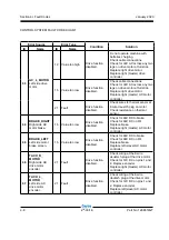
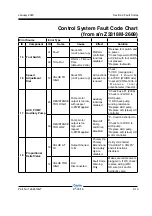
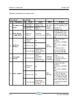
13 Refer to the fault code table on the following
pages to aid in troubleshooting the machine by
pinpointing the area or component affected.
14 To exit the fault code screen, momentarily
activate the drive enable toggle switch to the
left direction until
FAULTS
is shown on the
display.
To exit programming mode:
15 Push in the red Emergency Stop button at
the platform controls. Wait approximately 5
seconds and then pull out the red Emergency
Stop button out to the on position.
FAULT CODES
Summary of Contents for Genie Z-33/18
Page 6: ...vi Z 33 18 Part No 1268514GT January 2020 This page intentionally left blank ...
Page 12: ...xii Z 33 18 Part No 1268514GT January 2020 This page intentionally left blank ...
Page 104: ...5 2 Z 33 18 Part No 1268514GT January 2020 Section 5 Schematics Electrical Symbols Legends ...
Page 105: ...January 2020 Part No 1268514GT Z 33 18 5 3 Section 5 Schematics Hydraulic Symbols Legends ...
Page 106: ...January 2020 Section 5 Schematics 5 4 5 5 Electrical Schematic ...
Page 108: ...January 2020 Section 5 Schematics 5 7 Electrical Schematic ...
Page 110: ...January 2020 Section 5 Schematics 5 9 Electrical Schematic ...
Page 112: ...January 2020 Section 5 Schematics 5 11 Electrical Schematic ...
Page 114: ...January 2020 Section 5 Schematics 5 13 Electrical Schematic ...
Page 117: ...5 16 Z 33 18 Part No 1268514GT January 2020 Section 5 Schematics Hydraulic Schematic ...


