Service and Repair Manual
October 2021
Platform Controls
14
Z
®
-34/22 Bi-Energy
Part No. 1268515GT
1-1
Controllers
Platform Controls
The drive joystick is connected to the drive motor
controller located under the non-steer end drive
chassis cover. The drive motor controller can also
recognize machine drive malfunctions and display
controller fault codes by flashing a LED at the
ground controls. See the Troubleshooting section
of this manual for a list of fault codes and
additional information. There are no adjustments
needed on the drive joystick controller. For further
information or assistance, contact the Genie
Product Support.
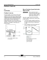
1 boom function speed controller
2 drive joystick
Boom Functi on Sp eed C ont roller Adjust ment s
Boom Function Speed Controller
Adjustments
Electrocution/burn hazard.
Contact with electrically charged
circuits could result in death or
serious injury. Remove all rings,
watches and other jewelry.
Note: Do not adjust the boom function speed
controller unless the static battery supply voltage
is above 24V DC.
1 Turn the key switch to platform controls and
pull out the red Emergency Stop button to the
on position at both the ground and platform
controls.
2 Open the platform control box lid and locate
the boom function speed controller.
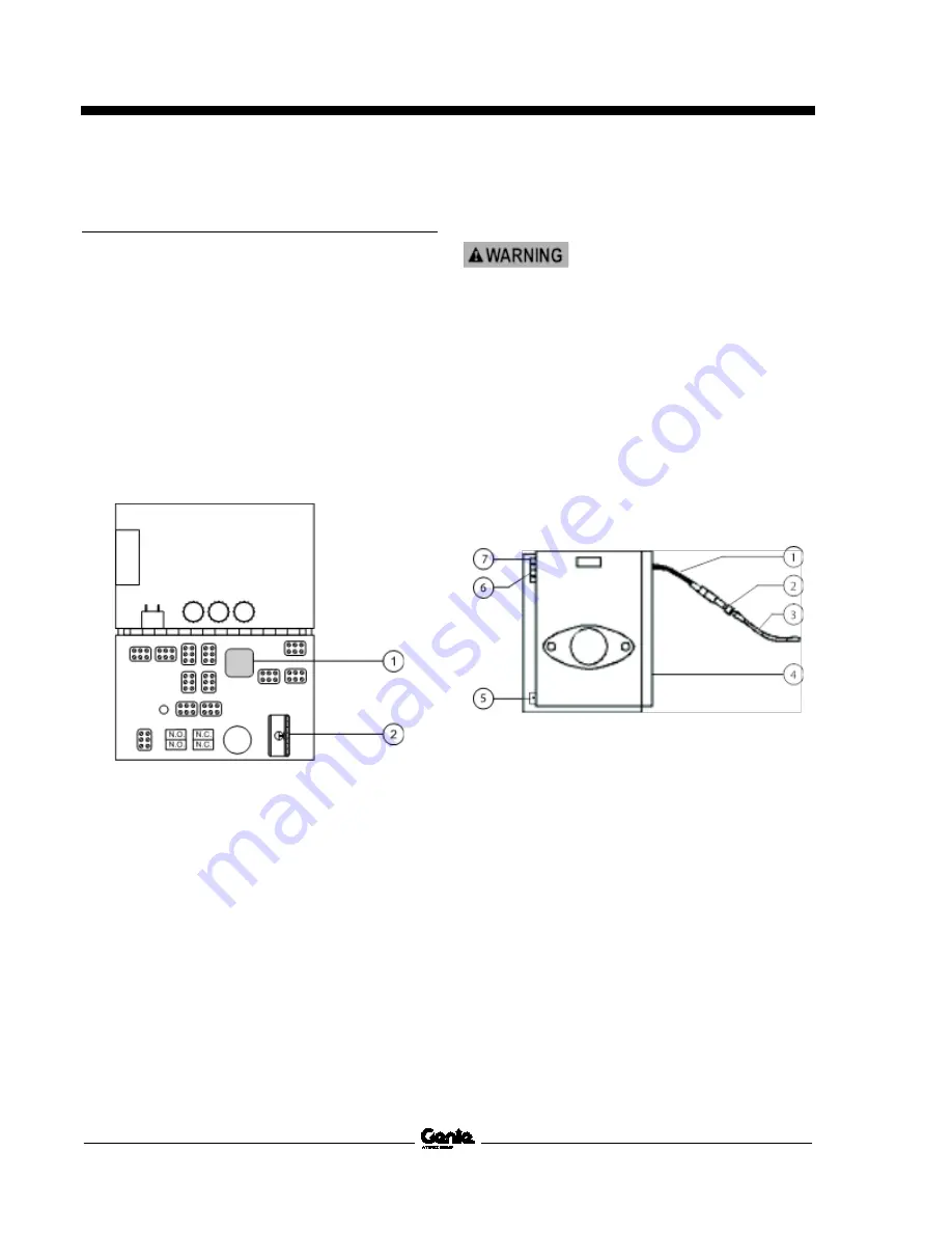
1 black/red wire
2 diode
3 white/red wire
4 boom function speed controller
5 ramp rate trimpot
6 threshold trimpot
7 max-out trimpot
Summary of Contents for Genie Z-34/22
Page 63: ...October 2021 Service and Repair Manual Manifolds Part No 1268515GT Z 34 22 Bi Energy 51 ...
Page 89: ...October 2021 Service and Repair Manual 77 Electrical Schematic ANSI CSA from SN Z34F 12066 ...
Page 92: ...Service and Repair Manual October 2021 80 Electrical Schematic ANSI CSA from SN Z34F 12066 ...
Page 97: ...October 2021 Service and Repair Manual 85 PBOX Wiring Diagram ANSI CSA from SN Z3414 9686 ...
Page 103: ...October 2021 Service and Repair Manual 91 Electrical Schematic CE AS from SN Z34F 12066 ...
Page 106: ...Service and Repair Manual October 2021 94 Electrical Schematic CE AS from SN Z34F 12066 ...
Page 114: ...Service and Repair Manual October 2021 102 Power Cable Wiring Diagram from SN Z3414 9686 ...
Page 115: ...October 2021 Service and Repair Manual 103 Drive Contactor Panel Wiring Diagram ...
Page 118: ...Service and Repair Manual October 2021 106 Manifold and Limit Switch Wiring Diagram ...
Page 119: ...October 2021 Service and Repair Manual 107 LVI BCI Option Wiring Diagram ...
Page 122: ...Service and Repair Manual October 2021 110 Charger Interlock Option ...
Page 123: ...October 2021 Service and Repair Manual 111 Engine Wiring Diagram ...
Page 126: ...Service and Repair Manual October 2021 114 Contact Alarm Option from SN Z34F 12066 ...
Page 127: ...October 2021 Service and Repair Manual 115 Fuel Level Sensor Option from SN Z34F 12066 ...
Page 129: ...October 2021 Service and Repair Manual 117 Hydraulic Schematic ...
Page 131: ......


