Service and Repair Manual
October 2021
Axle Components
60
Z
®
-34/22 Bi-Energy
Part No. 1268515GT
12-1
Yoke and Hub
How to Re mov e th e Yoke and Hub
How to Remove the Yoke and
Hub
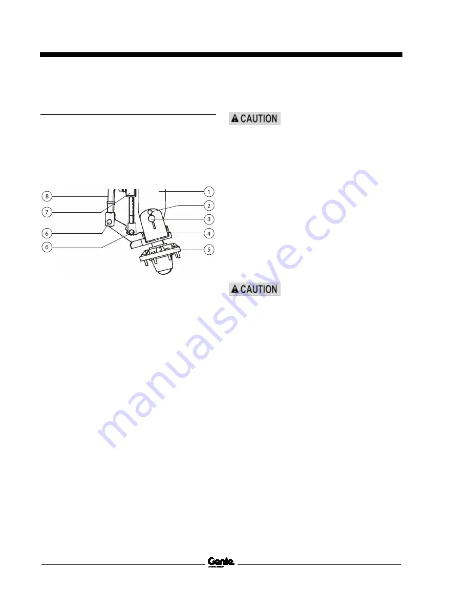
1 Remove the pin retaining fastener and the
clevis pin from both the steering cylinder and
the tie rod.
1 axle
2 pin retaining fastener
3 king pin
4 yoke
5 hub
6 clevis pin
7 steering cylinder
8 tie rod
2 Loosen the wheel lug nuts. Do not remove
them.
3 Block the non-steer wheels, and then center a
lifting jack under the steering axle.
4 Raise the machine 6 inches / 15 cm and place
blocks under the drive chassis for support.
5 Remove the lug nuts, then the tire and wheel
assembly.
6 Remove the pin retaining fasteners from the
upper and lower yoke pivot pins.
7 Support the yoke/hub assembly with a lifting
device.
8 Place a rod through the yoke pivot pins and
twist to remove the pins.
Crushing hazard. The yoke/hub
assembly may become
unbalanced and fall when the
yoke pivot pins are removed if it is
not properly supported and
secured to the lifting device.
How to Re mov e th e Hub and Beari ngs
How to Remove the Hub and
Bearings, 2WD Models
1 Loosen the wheel lug nuts. Do not remove
them.
2 Block the non-steer wheels and place a lifting
jack of ample capacity under the steer axle.
3 Raise the machine 6 inches / 15 cm and place
blocks under the chassis for support.
Crushing hazard. The machine
may fall if not properly
supported.
4 Remove the lug nuts. Remove the tire and
wheel assembly.
5 Remove the dust cap, cotter pin and castle
nut.
Note: Always use a new cotter pin when installing
a castle nut.
6 Pull the hub off the spindle. The washer and
outer bearing should fall loose from the hub.
7 Place the hub on a flat surface and gently pry
the bearing seal out of the hub.
8 Remove the rear bearing.
Summary of Contents for Genie Z-34/22
Page 63: ...October 2021 Service and Repair Manual Manifolds Part No 1268515GT Z 34 22 Bi Energy 51 ...
Page 89: ...October 2021 Service and Repair Manual 77 Electrical Schematic ANSI CSA from SN Z34F 12066 ...
Page 92: ...Service and Repair Manual October 2021 80 Electrical Schematic ANSI CSA from SN Z34F 12066 ...
Page 97: ...October 2021 Service and Repair Manual 85 PBOX Wiring Diagram ANSI CSA from SN Z3414 9686 ...
Page 103: ...October 2021 Service and Repair Manual 91 Electrical Schematic CE AS from SN Z34F 12066 ...
Page 106: ...Service and Repair Manual October 2021 94 Electrical Schematic CE AS from SN Z34F 12066 ...
Page 114: ...Service and Repair Manual October 2021 102 Power Cable Wiring Diagram from SN Z3414 9686 ...
Page 115: ...October 2021 Service and Repair Manual 103 Drive Contactor Panel Wiring Diagram ...
Page 118: ...Service and Repair Manual October 2021 106 Manifold and Limit Switch Wiring Diagram ...
Page 119: ...October 2021 Service and Repair Manual 107 LVI BCI Option Wiring Diagram ...
Page 122: ...Service and Repair Manual October 2021 110 Charger Interlock Option ...
Page 123: ...October 2021 Service and Repair Manual 111 Engine Wiring Diagram ...
Page 126: ...Service and Repair Manual October 2021 114 Contact Alarm Option from SN Z34F 12066 ...
Page 127: ...October 2021 Service and Repair Manual 115 Fuel Level Sensor Option from SN Z34F 12066 ...
Page 129: ...October 2021 Service and Repair Manual 117 Hydraulic Schematic ...
Page 131: ......


