October 2021
Service and Repair Manual
Engines
Part No. 1268515GT
Z
®
-34/22 Bi-Energy
41
3 Tighten the set screw on the pulley bushing
hand tight.
4 Slide the engine pulley onto the pulley
bushing.
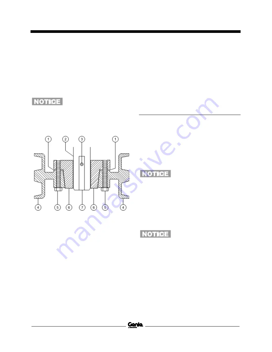
5 Install the pulley mounting bolts and tighten
them to specification. Refer to Specifications,
Generator Specifications
.
Component damage hazard. Do
not overtighten the pulley
mounting bolts. There must be a
gap visible between the engine
drive pulley and the pulley
bushing.
1 gap
2 shaft
3 set screw
4 engine drive pulley
5 engine drive pulley bolt
6 shaft bushing
7 woodruff key
6 Check the alignment between the engine
drive pulley and the generator pulley using a
straightedge. Refer to Specifications,
Generator.
Note: If the pulley alignment is not within
specification, remove the engine pulley and repeat
steps 2 through 6. Refer to Repair Procedure,
How
to Remove the Engine Drive Pulley.
Coolant Temperature and Oil
Pressure Switches
The engine coolant temperature switch is a
normally open switch. The switch contacts close at
approximately 225°F / 107°C. If the coolant
temperature rises above the switch point, the
switch contacts close and the engine will shut off
to prevent damage. The engine will not start until
the temperature drops below the switch point. An
over- temperature indicator light at the ground
controls should turn on when the switch closes.
Component damage hazard.Do
not crank the engine with the
over-temperature light on.
The engine oil switch is a normally closed switch.
The switch contacts open at approximately 7 psi /
0.48 bar. If the oil pressure drops below the switch
point, the contacts open and the engine will shut
off to prevent damage. A low oil pressure indicator
light at the ground controls should turn on when
the switch opens.
Component damage hazard.Do
not crank the engine with the low
oil pressure light on.
Summary of Contents for Genie Z-34/22
Page 63: ...October 2021 Service and Repair Manual Manifolds Part No 1268515GT Z 34 22 Bi Energy 51 ...
Page 89: ...October 2021 Service and Repair Manual 77 Electrical Schematic ANSI CSA from SN Z34F 12066 ...
Page 92: ...Service and Repair Manual October 2021 80 Electrical Schematic ANSI CSA from SN Z34F 12066 ...
Page 97: ...October 2021 Service and Repair Manual 85 PBOX Wiring Diagram ANSI CSA from SN Z3414 9686 ...
Page 103: ...October 2021 Service and Repair Manual 91 Electrical Schematic CE AS from SN Z34F 12066 ...
Page 106: ...Service and Repair Manual October 2021 94 Electrical Schematic CE AS from SN Z34F 12066 ...
Page 114: ...Service and Repair Manual October 2021 102 Power Cable Wiring Diagram from SN Z3414 9686 ...
Page 115: ...October 2021 Service and Repair Manual 103 Drive Contactor Panel Wiring Diagram ...
Page 118: ...Service and Repair Manual October 2021 106 Manifold and Limit Switch Wiring Diagram ...
Page 119: ...October 2021 Service and Repair Manual 107 LVI BCI Option Wiring Diagram ...
Page 122: ...Service and Repair Manual October 2021 110 Charger Interlock Option ...
Page 123: ...October 2021 Service and Repair Manual 111 Engine Wiring Diagram ...
Page 126: ...Service and Repair Manual October 2021 114 Contact Alarm Option from SN Z34F 12066 ...
Page 127: ...October 2021 Service and Repair Manual 115 Fuel Level Sensor Option from SN Z34F 12066 ...
Page 129: ...October 2021 Service and Repair Manual 117 Hydraulic Schematic ...
Page 131: ......


