September 2016
Service and Repair Manual
Platform Controls
Part No. 1268528
Z-40/23N, Z-40/23N RJ
19
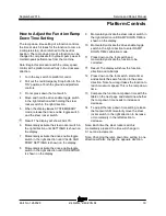
How to Adj ust the Functi on R amp D ow n Tim e Setting
How to Adjust the Function Ramp
Down Time Setting
The ramp down time setting of a function controls
the time at which it takes for the function to come to
a complete stop, when returned to the neutral
position. The ramp down time of a function can be
changed to compensate for hydraulic pump wear to
maintain peak performance from the machine.
Note: Begin this procedure with the rotary speed
control at the platform turned fully in the clockwise
direction.
1 Turn the key switch to platform control.
2 Pull out the red Emergency Stop button to the
'ON' position at both the ground and platform
controls.
3 Do not press down the foot switch.
4 Move and hold the drive enable toggle switch
in the right direction while holding the steer
rocker switch in the right direction.
5 When the display leaves SYSTEM READY
mode, release the drive enable toggle switch
and the steer rocker switch.
Result: The display will show FAULTS.
6 Momentarily activate the steer rocker switch in
the right direction until SETTINGS is shown on
the display.
7 Momentarily activate the drive enable toggle
switch in the right direction until VALVE AND
PUMP SETTINGS is shown on the display.
8 Momentarily activate the drive enable toggle
switch in the right direction until THRESHOLD
is shown on the display.
9 Momentarily activate the steer rocker switch in
the right direction until RAMP DOWN TIME is
shown on the display.
10 Momentarily activate the drive enable toggle
switch in the right direction to enter RAMP
DOWN TIME calibration mode.
11 Press down on the foot switch and
momentarily activate the function to be
corrected.
Result: The display will show the function,
direction and milliamps.
12 Press down on the foot switch, start a timer
and activate the same function in the same
direction. Note how long it takes the function to
reach maximum speed. This is the ramp down
time.
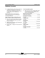
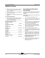
13 Compare the function ramp down time with the
table on the next page and determine whether
the ramp down time needs to increase or
decrease.
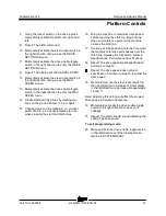
14 To adjust the ramp down time setting, release
the foot switch. Momentarily move the steer
rocker switch in the right direction to increase
or momentarily in the left direction to
decrease.
Note: Each time the steer rocker switch is
momentarily pressed, the time will change in
0.1 second increments.
Note: Changing the ramp down time setting in one
direction will also change the opposite direction.
Summary of Contents for Genie Z-40/23N
Page 63: ...September 2016 Service and Repair Manual Manifolds Part No 1268528 Z 40 23N Z 40 23N RJ 53 ...
Page 111: ...September 2016 Service and Repair Manual 101 Electrical Schematic Chassis ...
Page 114: ...Service and Repair Manual September 2016 104 Electrical Schematic Ground Controls ...
Page 115: ...September 2016 Service and Repair Manual 105 Electrical Schematic Platform Controls ...
Page 118: ...Service and Repair Manual September 2016 108 Ground Control Box Wiring Diagram ...
Page 119: ...September 2016 Service and Repair Manual 109 Platform Control Box Wiring Diagram ...
Page 122: ...Service and Repair Manual September 2016 112 Platform Control Box Wiring Diagram Options ...
Page 123: ...September 2016 Service and Repair Manual 113 Hydraulic Schematic ...
Page 125: ......


