Service and Repair Manual
November 2020
Manifolds
70
Z
®
-45 XC
™
• Z
®
-45 HF
Part No. 1268197GT
8-6
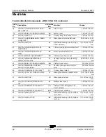
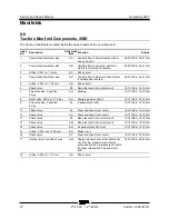
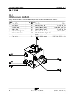
Traction Manifold Components, 4WD
The traction manifold is mounted inside the drive chassis at the non-steer end.
Index
No.
Description
Schematic
Item
Function
Torque
1
Flow divider/combiner valve
AA
Controls flow to flow divider/combiner
valves 2 and 4
25-30 ft-lbs / 34-41 Nm
2
Flow divider/combiner valve
AB
Controls flow to non-steer end drive
motors in forward and reverse
25-30 ft-lbs / 34-41 Nm
3
Orifice, 0.047 in / 1.2 mm
AC
Drive circuit
4
Flow divider/combiner valve
AD
Controls flow to steer end drive motors
in forward and reverse
25-30 ft-lbs / 34-41 Nm
5
Orifice, 0.040 in / 1.02 mm
AE
Drive circuit
6
Check valve
AF
Non-steer end drive motor circuit
10-12 ft-lbs / 14-16 Nm
7
Solenoid valve, 2 position
3 way
AG
Braking
10-12 ft-lbs / 14-16 Nm
8
Relief valve, 250 psi / 17.2 bar
AH
Charge pressure circuit
10-12 ft-lbs / 14-16 Nm
9
Solenoid valve, 2 position
3 way
AI
2-speed motor shift
10-12 ft-lbs / 14-16 Nm
10
Check valve
AJ
Steer end drive motor circuit
10-12 ft-lbs / 14-16 Nm
11
Check valve
AK
Steer end drive motor circuit
10-12 ft-lbs / 14-16 Nm
12
Check valve
AL
Non-steer end drive motor circuit
10-12 ft-lbs / 14-16 Nm
13
Check valve
AM
Non-steer end drive motor circuit
10-12 ft-lbs / 14-16 Nm
14
Check valve
AN
2 speed motor shift circuit
10-12 ft-lbs / 14-16 Nm
15
Orifice, 0.030 inch / 0.76 mm
AO
Brake circuit
16
Check valve
AP
Steer end drive motor circuit
10-12 ft-lbs / 14-16 Nm
17
Shuttle valve, 3 position 3 way
AQ
Charge pressure circuit that directs hot
oil out of low pressure side of drive
pump and allows low pressure flow path
for brake release and 2-speed motor
shift
15-18 ft-lbs / 20-24 Nm
18
Orifice, 0.040 in / 1.01 mm
AR
Drive circuit
Summary of Contents for Genie Z-45 XC
Page 69: ...November 2020 Service and Repair Manual Manifolds Part No 1268197GT Z 45 XC Z 45 HF 57 ...
Page 71: ...November 2020 Service and Repair Manual Manifolds Part No 1268197GT Z 45 XC Z 45 HF 59 ...
Page 73: ...November 2020 Service and Repair Manual Manifolds Part No 1268197GT Z 45 XC Z 45 HF 61 ...
Page 75: ...November 2020 Service and Repair Manual Manifolds Part No 1268197GT Z 45 XC Z 45 HF 63 ...
Page 83: ...November 2020 Service and Repair Manual Manifolds Part No 1268197GT Z 45 XC Z 45 HF 71 ...
Page 143: ...November 2020 Service and Repair Manual 131 Electrical Schematic Ford MSG425 ...
Page 147: ...November 2020 Service and Repair Manual 135 Electrical Schematic Deutz D 2 9 L4 ...
Page 150: ...Service and Repair Manual November 2020 138 Engine Wire Harness Deutz D 2 9 L4 ...
Page 151: ...November 2020 Service and Repair Manual 139 Electrical Schematic Deutz TD 2 2 L3 ...
Page 154: ...Service and Repair Manual November 2020 142 Engine Wire Harness Deutz TD 2 2 L3 Page 1 ...
Page 156: ...Service and Repair Manual November 2020 144 Engine Wire Harness Deutz TD 2 2 L3 Page 2 ...
Page 157: ...November 2020 Service and Repair Manual 145 Electrical Schematic Perkins 404F E22T ...
Page 160: ...Service and Repair Manual November 2020 148 Engine Wire Harness Perkins 404F E22T ...
Page 161: ...November 2020 Service and Repair Manual 149 Electrical Schematic Function Controls ANSI CSA ...
Page 164: ...Service and Repair Manual November 2020 152 Electrical Schematic Function Controls CE ...
Page 165: ...November 2020 Service and Repair Manual 153 Electrical Schematic Platform Overload ...
Page 168: ...Service and Repair Manual November 2020 156 Electrical Schematic Options Wiring Diagram ...
Page 181: ...November 2020 Service and Repair Manual 169 Ground Control Box Switch Panel Wiring Diagram CE ...
Page 185: ...November 2020 Service and Repair Manual 173 Platform Control Box Switch Panel Wiring Diagram ...
Page 192: ...Service and Repair Manual November 2020 180 Platform Control Box Relay Wiring Diagram CE ...
Page 193: ...November 2020 Service and Repair Manual 181 Hydraulic Schematic CE to Z4525XCM 1500 ...
Page 197: ......


