background image

Service and Repair Manual


December 2018


Hydraulic Pumps 


40 

Z®-60/37 DC • Z®-60

/37 FE 

Part No. 1271125GT 


7-1 
Function Pump 

How to Remove the Function 
Pump 

Note: When removing a hose assembly or fitting, 
the O-ring (if equipped) on the fitting and/or hose 
end must be replaced. All connections must be 
torqued to specification during installation. Refer to 
Specifications, 

Hydraulic Hose and Fitting Torque 

Specifications.


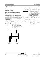
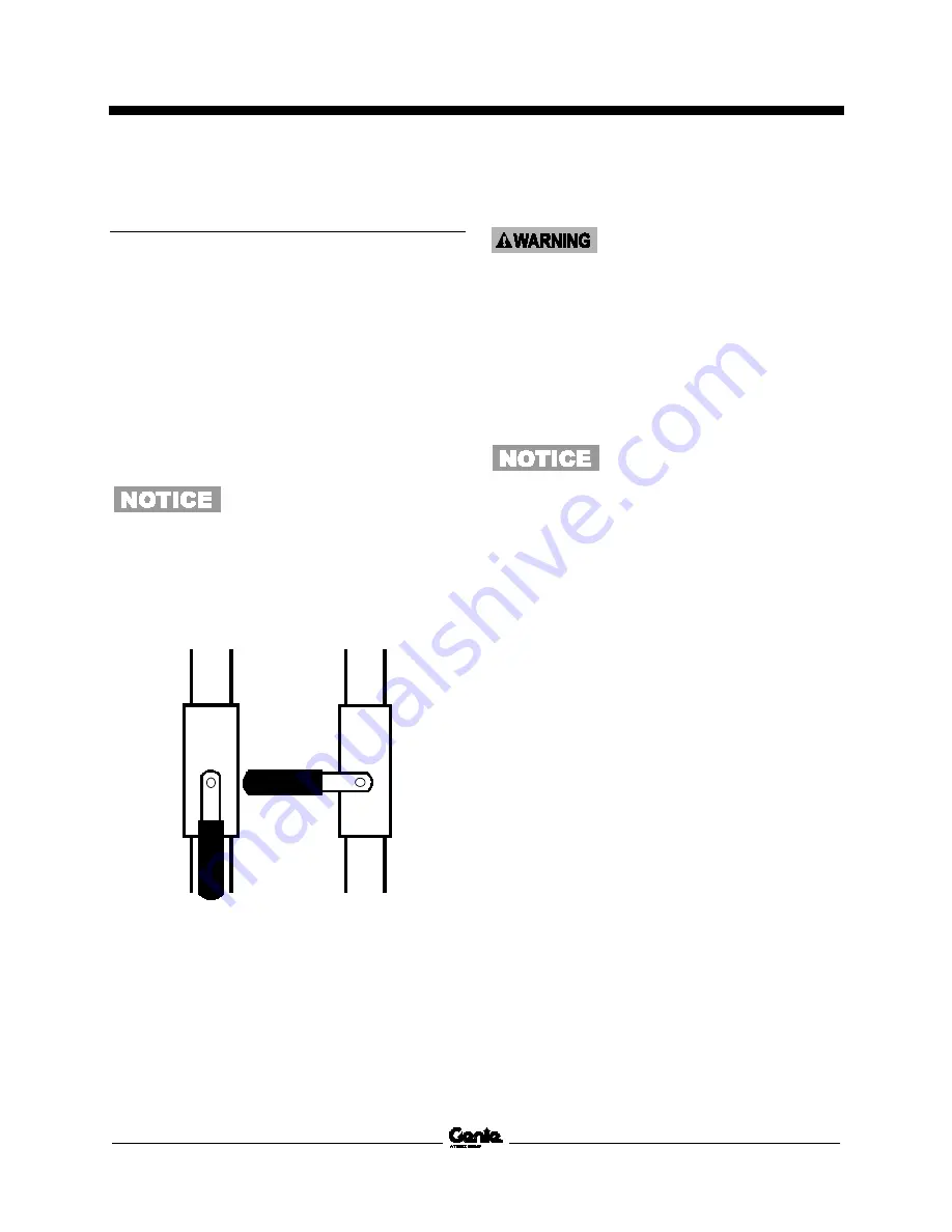
Locate the hydraulic tank valve at the hydraulic 
tank. Close the valve. 


Component Damage 
hazard.Do not perform any 
functions with hydraulic tank 
shut off valve closed. Remove 
the key switch and tag the 
machine to inform personnel of 
the condition. 


Open 

Closed 


2   Tag, disconnect and plug function pump 

hydraulic hoses. Cap the fittings on the pump. 


Bodily injury hazard. Spraying 
hydraulic oil can penetrate and 
burn skin. Loosen hydraulic 
connections very slowly to allow 
the oil pressure to dissipate 
gradually. Do not allow oil to 
squirt or spray. 

Support the pump with a suitable lifting device. 

Remove the pump mounting bolts. Carefully 
remove the pump. 


Component damage hazard. 
Be sure to open the hydraulic 
tank valve and prime the pump 
after installation. 


Summary of Contents for Genie Z-60 DC

Page 1: ...6N 101 to Z6016N 599 from Z60N 600 This manual includes Repair procedures Fault Codes Electrical and Hydraulic Schematics Z 60 37 FE For detailed maintenance procedures refer to the appropriate Maintenance Manual for your machine Part No 1271125GT Rev A6 December 2018 ...

Page 2: ...by ISO 16368 Machine Design Life Unrestricted with proper operation inspection and scheduled maintenance Technical Publications Genie has endeavored to deliver the highest degree of accuracy possible However continuous improvement of our products is a Genie policy Therefore product specifications are subject to change without notice Readers are encouraged to notify Genie of errors and send in sugg...

Page 3: ...sure Sensor Updated A2 9 2016 Introduction Serial number Legend A3 12 2016 Schematic Power Cable Wiring Diagram A4 11 2017 Specifications Machine Specifications A5 5 2018 Schematic Corrected Options Schematic A6 12 2018 Specifications Rotate hub torque value Reference Examples Electronic Version Click on any content or procedure in the Table of Contents to view the update Section Repair Procedure ...

Page 4: ...Serial Number Legend To August 31 2016 1 Model 2 Model year 3 Facility code 4 Sequence number 5 Serial number stamped on chassis 6 Serial label located under cover From September 1 2016 1 Model 2 Facility code 3 Sequence number 4 Serial number stamped on chassis 5 Serial label located under cover ...

Page 5: ...njury Many of the hazards identified in the operator s manual are also safety hazards when maintenance and repair procedures are performed Do Not Perform Maintenance Unless R You are trained and qualified to perform maintenance on this machine R You read understand and obey manufacturer s instructions and safety rules employer s safety rules and worksite regulations applicable governmental regulat...

Page 6: ...ntial crushing hazards such as moving parts free swinging or unsecured components when lifting or placing loads Always wear approved steel toed shoes Workplace Safety Any person working on or around a machine must be aware of all known safety hazards Personal safety and the continued safe operation of the machine should be your top priority Be sure to keep sparks flames and lighted tobacco away fr...

Page 7: ...ion 1 Safety Rules v General Safety Rules v Section 2 Specifications 1 Machine Specifications 1 Performance Specifications 2 Hydraulic Specification 2 Hydraulic Component Specifications 5 Manifold Component Specifications 6 Kubota D1105 Engine Specifications 7 Machine Torque Specifications 8 Machine Component Weights 8 Hydraulic Hose and Fitting Torque Specifications 9 Torque Procedure 10 ...

Page 8: ...alibrate Booms Angle Sensors 21 1 3 How to Clear the Fault History 22 Platform Components 22 2 1 Platform Leveling Slave Cylinder 22 2 2 Platform Rotator 24 2 3 Platform Overload System 25 2 4 How to Reset Overload Recovery Message 27 Jib Boom Components 28 3 1 Jib Boom 28 3 2 Jib Boom Lift Cylinder 29 Primary Boom Components 30 4 1 Cable Track 30 How to Repair the Cable Track 31 4 2 Primary Boom ...

Page 9: ...djust the Platform Level Up Relief Valve 48 How to Adjust the Primary Boom Extend Relief Valve 49 8 3 Jib Boom Platform Rotate Manifold Components 50 8 4 Turntable Rotation Manifold Components 51 8 5 Oscillate Directional Valve Manifold Components 52 8 6 How to Set Up the Oscillate Directional Valve 53 How to Adjust the Oscillate Reducing Valve 53 How to Test a Coil Diode 55 Turntable Rotation Com...

Page 10: ...ical Symbol Legend 86 Hydraulic Symbols Legend 87 Electrical Component and Wire Color Legends 88 Kubota Engine Fuse and Relay Module 91 12V DC Charger Wiring DC Option 92 AC Input Wiring DC Option 93 CAN BUS Wiring Diagram DC Models 94 Limit Switch Angle Sensor Legend 95 Electrical Schematics Options 97 Wiring Diagram Options 98 Schematics Options 4WD DC and FE Models 99 Power Cable Wiring Diagram...

Page 11: ...80 ft lbs 244 Nm Overall tire diameter Rough terrain low profile tires 36 9 in 93 7 cm Fluid capacities Fuel tank 17 gallons 64 4 liters Hydraulic tank 18 gallons 68 liters Hydraulic system including tank 21 gallons 80 liters Drive hubs 24 fl oz 710 cc Turntable rotation drive hub 43 fl oz 1262 cc Drive hub oil type SAE 90 multipurpose hypoid gear oil API service classification GL5 Batteries Type ...

Page 12: ...igned to give maximum protection to hydraulic systems have the ability to perform over a wide temperature range and the viscosity index should exceed 140 They should provide excellent antiwear oxidation prevention corrosion inhibition seal conditioning and foam and aeration suppression properties Cleanliness level minimum ISO 15 13 Water content maximum 250 ppm Recommended Hydraulic Fluid Hydrauli...

Page 13: ...ove 120 F 49 C Hydraulic Fluid Temperature Range Ambient air temperature 1 Chevron hydraulic oil 5606A 2 Petro Canada Environ MV 46 3 UCON Hydrolube HP 5046D 4 Chevron Rando HD premium oil MV Chevron Rando HD Premium Oil MV Fluid Properties ISO Grade 32 Viscosity index 200 Kinematic Viscosity cSt 200 F 100 C cSt 104 F 40 C 7 5 33 5 Brookfield Viscosity cP 4 F 20 C cP 22 F 30 C 1040 3310 Flash poin...

Page 14: ...ing system is used Continued use of Chevron 5606A hydraulic fluid or equivalent when ambient temperatures are consistently above 32 F 0 C may result in component damage Petro Canada Environ MV 46 Fluid Properties ISO Grade 46 Viscosity index 154 Kinematic Viscosity cSt 200 F 100 C cSt 104 F 40 C 8 0 44 4 Flash point 482 F 250 C Pour point 49 F 45 C Maximum continuous operating temperature 180 F 82...

Page 15: ... inner pump outer pump 40 cu in 6 6 cc 20 cu in 3 3 cc Max flow rate L min inner pump L min outer pump 6 8 gpm 25 74 3 4 gpm 12 87 Auxiliary Pump Type Fixed displacement gear pump Displacement per revolution 1 7 gpm 6 44 L min Function manifold Proportional relief valve pressure variable 50 to 3000 psi 3 4 to 207 bar Platform level relief valve pressure 2800 psi 193 bar Primary boom extend relief ...

Page 16: ...t temperature of 68 F 20 C As valve coil resistance is sensitive to changes in air temperature the coil resistance will typically increase or decrease by 4 for each 18 F 10 C that your air temperature increases or decreases from 68 F 20 C Description Specification Proportional solenoid relief valve 24V DC schematic item AA 22 Ω Proportional solenoid valve 3 position 4 way 20V DC schematic items B ...

Page 17: ...sity requirements Below 10 C 14 F SAE 10W 30 10 to 25 C 14 to 77 F SAE 10W 30 SAE 15W 40 Above 25 C 77 F SAE30 SAE10W 30 SAE15W 40 Unit ships with 15W 40 Extreme operating temperatures may require the use of alternative engine oils For oil requirements refer to the Engine Operator Manual for your engine Engine coolant Capacity 3 3 quarts 3 1 liters Fuel injection system Injection pump make Bosch M...

Page 18: ...ve motor leads square nuts requires 12 point socket 9 ft lbs 12 Nm Machine Component Weights Tire and wheel assembly 429 lbs 195 kg Drive motor and hub 160 lbs 73 kg Engine assembly 724 lbs 328 kg Primary boom 1277 lbs 579 kg Primary boom cylinder 272 lbs 123 kg Primary boom extend cylinder 234 lbs 106 kg Secondary boom linkage 3017 lbs 1368 kg Secondary boom cylinder 180 lbs 82 kg Jib boom assemb...

Page 19: ...9 16 18 1 8 3 4 16 1 10 7 8 14 1 12 1 1 16 12 1 16 1 5 16 12 1 20 1 5 8 12 1 24 1 7 8 12 1 SAE O ring Boss Port tube fitting installed into Aluminum all types SAE Dash Size Torque 4 14 ft lbs 19 Nm 6 23 ft lbs 31 2 Nm 8 36 ft lbs 54 2 Nm 10 62 ft lbs 84 Nm 12 84 ft lbs 114 Nm 16 125 ft lbs 169 5 Nm 20 151 ft lbs 204 7 Nm 24 184 ft lbs 249 5 Nm Adjustable Fitting Non adjustable fitting 1 jam nut SA...

Page 20: ... seated and retained properly 4 Position the tube and nut squarely on the face seal end of the fitting and tighten the nut finger tight 5 Tighten the nut or fitting to the appropriate torque Refer to the appropriate torque chart in this section 6 Operate all machine functions and inspect the hose fittings and related components to confirm there are no leaks JIC 37 fittings 1 Align the tube flare h...

Page 21: ...correct number of flats for the proper tightening position Note The marks indicate the correct tightening positions have been determined Use the second mark on the body hex fitting to properly tighten the joint after it has been loosened Illustration 2 1 body hex fitting 2 reference mark 3 second mark 4 Tighten the hex nut until the mark on the hex nut is aligned with the second mark on the body h...

Page 22: ...anual on your machine R Be sure that all necessary tools and parts are available and ready for use R Use only Genie approved replacement parts R Read each procedure completely and adhere to the instructions Attempting shortcuts may produce hazardous conditions Machine Configuration R Unless otherwise specified perform each repair procedure with the machine in the following configuration Machine pa...

Page 23: ... to alert personnel to potential personal injury hazards Obey all safety messages that follow this symbol to avoid possible injury or death Indicates a imminently hazardous situation which if not avoided will result in death or serious injury Indicates a potentially hazardous situation which if not avoided could result in death or serious injury Indicates a potentially hazardous situation which if...

Page 24: ...rocedures How to Calibrate Booms Angle Sensors Note The one point calibration is optional It allows 2 MPH 3 2 Km h travel if machine needs to be immediately moved 5 Calibrate the steer angle sensor Refer to Repair Procedures How to Calibrate the Steer Angle Sensor 6 Complete calibrating the Primary and Secondary angle sensors stowed and elevated positions Refer to Repair Procedures How to Calibrat...

Page 25: ...n Automatic calibration of center voltage occurs on power up if the signal value is in the valid range Each joystick controller should operate smoothly and provide proportional speed control over its entire range of motion The remaining boom functions operate by on off toggle switches Except for platform level the speed of these functions are controlled by a function speed control switch The platf...

Page 26: ...e toggle switch and steer joystick Result The display will show FAULTS 6 Momentarily activate steer in the right direction until SETTINGS is shown on the display 7 Momentarily activate the drive enable toggle switch in the right direction until VALVE AND SENSOR SETTINGS is shown on the display 8 Momentarily activate the drive enable toggle switch in the right direction until CALIBRATE TILT SENSOR ...

Page 27: ...p Down Primary Extend Retract Secondary Up Down and Turntable rotate Low flow Functions Jib Up Down Jib rotate and Platform rotate Other Functions Steering is set by a fixed flow regulating valve non adjustable Platform level adjusted by a needle valve located on the function manifold and Hydraulic Valve Ramps Refer to How to Adjust Ramp Rate Setting Note Refer to Specifications Performance Specif...

Page 28: ...on switch or joystick to full speed in the same direction Momentarily active steer left once every three seconds to decrease the maximum mA value where pressure rises to about 3000 PSI 207 bar and an audible alarm sounds Note The turntable function will only increase 300 PSI and no audible alarm When the 300 PSI occurs proceed to the next step 14 Release the foot switch and momentarily activate st...

Page 29: ... display shows the name of the function direction and current value in milliamps for the function being moved Example JIB_UP_MAX 590 20 Activate the boom function again by pressing the foot switch and moving the function switch in the same direction Using a stop watch record the full motion function and compare this time to the performance specification 21 While performing the function activate st...

Page 30: ...h and the steer joystick Result The display will show FAULTS 6 Momentarily activate steer in the right direction until SETTINGS is shown on the display 7 Momentarily activate the drive enable toggle switch in the right direction until VALVE AND SENSOR SETTINGS is shown on the display 8 Momentarily activate the drive enable toggle switch in the right direction until CALIBRATE TILT SENSOR is shown o...

Page 31: ...whether the boom sections are stowed or not stowed A two point calibration procedure captures the signal with the cylinder fully extended and fully retracted to an angle measurement that is scaled to degrees within the program If either angle sensor is in the uncalibrated state drive speed is limited to out of stowed speed Note Start this procedure with the boom in a stowed position Position the m...

Page 32: ...odes shown in the fault history menu 1 being the most recent displayed It may be necessary to clear the fault history in order to acquire the most recent fault codes It is also good practice to clear fault history after performing any calibration procedure Note Perform this procedure with the boom in the stowed position Refer to Navigation Menus Faults Menu 1 Turn the key switch to platform contro...

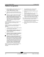
Page 33: ...he entire weight of the jib boom on the blocks 4 Tag disconnect and cap the hydraulic hoses from the slave cylinder Plug the union hoses from the master cylinder together using a connector Bodily injury hazard Spraying hydraulic oil can penetrate and burn skin Loosen hydraulic connections very slowly to allow the oil pressure to dissipate gradually Do not allow oil to squirt or spray 5 Remove the ...

Page 34: ...tions very slowly to allow the oil pressure to dissipate gradually Do not allow oil to squirt or spray 3 Support the platform rotator with an appropriate lifting device Do not apply any lifting pressure Crushing hazard The platform rotator may become unbalanced and fall if not properly supported How to Bleed the Platform Rotator Note This procedure will require two people Do not start the engine U...

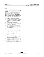
Page 35: ...h directions and inspect the bleed screws for leaks 2 3 Platform Overload System if equipped How to Calibrate the Platform Overload System Calibrating the platform overload system regularly is essential to safe machine operation Continued use of an improperly operating platform overload system could result in the system not sensing an overloaded platform condition Machine stability could be compro...

Page 36: ...mum rated load Result The overload indicator light is flashing at both the ground and platform controls the alarm is sounding Proceed to step 8 Result The overload indicator lights are off at the platform and ground controls the alarm does not sound Slowly loosen the load spring adjustment nut in a counterclockwise direction in 10 increments until the overload indicator light flashes at both the p...

Page 37: ... switch 4 Move and hold the drive enable toggle switch and steer in the right direction 5 When the display leaves SYSTEM READY mode release the drive enable toggle switch and the steer joystick Result The display will show FAULTS 6 Momentarily activate the drive enable toggle switch in the right direction until ACTIVE FAULTS is shown on the display 7 Activate steer in the right direction until RES...

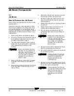
Page 38: ...astener from the jib boom lift cylinder rod end pivot pin Do not remove the pin 6 Slide both of the jib boom leveling arms off of the jib boom cylinder rod end pivot pin 7 Remove the hose and cable cover from the side of the jib boom Remove the hose and cable separators 8 Attach a lifting strap from an overhead crane to the jib boom 9 Support the barrel end of the jib boom lift cylinder with a sui...

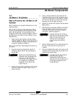
Page 39: ... dissipate gradually Do not allow oil to squirt or spray 3 Remove the pin retaining fasteners from the jib boom lift cylinder rod end pivot pin Do not remove the pin 4 Use a soft metal drift to tap the jib boom lift cylinder rod end pivot pin out enough to lower one of the leveling arms to the ground Tap the pin the other direction and lower the opposite leveling arm Do not remove the pin 5 Suppor...

Page 40: ...color of the connectors to those on the control box to be sure they are installed in the correct location 2 Disconnect the power to plat cable from the AC outlet box 3 Remove the hose and cable clamps from the platform support 4 Tag disconnect and plug the platform leveling slave cylinder hydraulic hoses from the bulkhead fittings on the top of the primary boom Cap the bulkhead fittings Bodily inj...

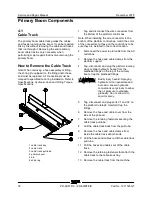
Page 41: ...replacement cable track section to the existing cable track using the snap rings 7 Install the rollers onto the new section of cable track 8 Operate the boom extend retract function through a full cycle to ensure smooth operation of the new section of cable track 4 2 Primary Boom How to Remove the Primary Boom Bodily injury hazard This procedure requires specific repair skills lifting equipment an...

Page 42: ...ray located under the primary boom and set it on a supporting device 13 Remove the retaining fasteners from the primary boom pivot pin 14 Remove the primary boom pivot pin with a soft metal drift then carefully remove the primary boom from the machine and place it on a structure capable of supporting it Crushing hazard The primary boom could become unbalanced and fall when removed from the machine...

Page 43: ...e to the primary boom for support 5 Raise the primary boom with the overhead crane slightly to take the pressure off the primary boom lift cylinder pivot pins 6 Support the rod end and the barrel end of the primary boom lift cylinder with a second overhead crane or similar lifting device 7 Tag disconnect and plug the primary boom lift cylinder hydraulic hoses Cap the fittings on the cylinder Bodil...

Page 44: ... remove the cover from the end of the the 1 boom tube 3 At the pivot end of the boom remove the retaining fasteners and blocks securing the extend cylinder to the 2 boom tube through the access holes in the 1 boom tube 4 At the pivot end of the boom remove the retaining fasteners and blocks securing the extend cylinder to the 1 boom tube 5 Tag disconnect and plug the primary boom extension cylinde...

Page 45: ...il both the rod end and barrel end pivot pins on the master cylinder are accessible 2 Use an overhead supporting device to support the platform Do not apply lifting pressure 3 Tag disconnect and plug the master cylinder hydraulic hoses Cap the fittings on the cylinder Bodily injury hazard Spraying hydraulic oil can penetrate and burn skin Loosen hydraulic connections very slowly to allow the oil p...

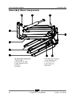
Page 46: ... 60 37 DC Z 60 37 FE Part No 1271125GT Secondary Boom components 1 master cylinder 2 primary boom lift cylinder 3 upper compression arms 4 mid pivot 5 timing link 6 secondary boom lift cylinder 7 lower compression arm 8 lower tension arms 9 upper tension arm 10upper pivot ...

Page 47: ...ary boom until the barrel end pivot pins of the secondary lift cylinder clear the lower tension arms 2 Attach a lifting strap from an overhead crane 5 ton 5000 kg to the pivot end of the primary boom for support Do not apply lifting pressure Crushing hazard The boom assembly can fall if not properly supported by the overhead crane Component damage hazard Hoses and cables can be damaged if they are...

Page 48: ...teners to 110 ft lbs 149 Nm dry 10 Lift and move the cylinder towards the center of the machine enough to lower it down through the lower compression arm Pull the cylinder towards the platform and remove it from the machine Crushing hazard The secondary boom lift cylinder could become unbalanced and fall when removed from the machine if not properly attached to the overhead crane Component damage ...

Page 49: ...der the engine tray and pull the engine out 2 Remove the high idle solenoid from the bracket 1 tach sensor 2 high idle solenoid 3 Locate tag and disconnect the tach sensor harness 4 Loosen the jam nut and remove the tach sensor 5 Thread the new tach sensor until it stops Note Do not over tighten 6 Back the tach sensor off 1 2 turn and tighten the jam nut 7 Start the engine and check the high idle ...

Page 50: ... Component Damage hazard Do not perform any functions with hydraulic tank shut off valve closed Remove the key switch and tag the machine to inform personnel of the condition Open Closed 2 Tag disconnect and plug function pump hydraulic hoses Cap the fittings on the pump Bodily injury hazard Spraying hydraulic oil can penetrate and burn skin Loosen hydraulic connections very slowly to allow the oi...

Page 51: ...toggle switch in the right direction while holding steer in the right direction 3 When the display leaves SYSTEM READY mode release the drive enable toggle switch and the steer joystick 4 Momentarily activate steer in the right direction until SETTINGS is shown on the display 5 Momentarily activate the drive enable toggle switch in the right direction until you see the VALVE AND SENSOR SETTINGS sc...

Page 52: ...Service and Repair Manual December 2018 Manifolds 42 Z 60 37 DC Z 60 37 FE Part No 1271125GT This page intentionally left blank ...

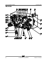
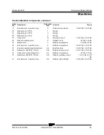
Page 53: ...ary boom retract 30 35 ft lbs 41 47 Nm 7 Solenoid valve 3 position 4 way G Secondary boom extend retract 30 35 ft lbs 41 47 Nm 8 Shuttle valve H Pilots primary boom retract counterbalance valve 4 5 ft lbs 5 7 Nm 9 Solenoid valve 2 position 2 way normally open I P2 circuit 19 21 ft lbs 26 29 Nm 10 Pressure transducer J Monitors pressure 18 20 ft lbs 25 27 Nm 11 Diagnostic port TP1 K Testing 12 Chec...

Page 54: ...Service and Repair Manual December 2018 Manifolds 44 Z 60 37 DC Z 60 37 FE Part No 1271125GT ...

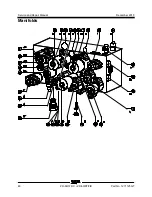
Page 55: ... Nm 24 Pressure reducing valve X Oscillate circuit 25 ft lbs 40 Nm 25 Needle valve Y Platform level up down 20 ft lbs 27 Nm 26 Solenoid valve 3 position 4 way Z Platform level up down 18 20 ft lbs 25 27 Nm 27 Solenoid operated proportional valve AA Boom functions 18 20 ft lbs 25 27 Nm 28 Relief valve 2800 PSI 193 bar AB Platform level up circuit 19 21 ft lbs 25 27 Nm 29 Check valve dual pilot oper...

Page 56: ...Service and Repair Manual December 2018 Manifolds 46 Z 60 37 DC Z 60 37 FE Part No 1271125GT ...

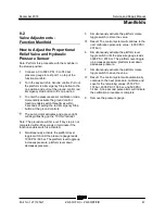
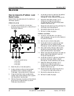
Page 57: ... begin flashing on the TCON controller Note The procedure will time out if any step is not completed within 90 seconds or terminate if the function enable switch is activated 4 Simultaneously activate the platform level toggle switch until the pressure gauge reads 1000 PSI 69 bar The platform level toggle up increases pressure platform level down decreases pressure 5 Simultaneously activate the pl...

Page 58: ...lockwise to increase the pressure or counterclockwise to decrease the pressure Install the relief valve cap 8 Repeat this procedure beginning with step 3 to confirm the relief valve pressure 9 Reinstall the proportional valve coil 10 Remove the pressure gauge Platform Level Down 11 Connect a 0 to 5000 PSI 0 to 350 bar pressure gauge to test port 4 on the bottom of the function manifold 12 Raise th...

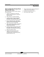
Page 59: ...n Manifold Components 4 Press and hold the function enable button Activate and hold the primary boom extend switch with the boom fully extended 5 Observe the pressure reading on the pressure gauge Refer to Specifications Hydraulic Component Specifications 6 Locate and remove the cap from the primary boom extend relief valve Refer to Repair Procedures Function Manifold Components 7 Remove the press...

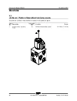
Page 60: ...rt No 1271125GT 8 3 Jib Boom Platform Rotate Manifold Components The jib boom platform rotate manifold is mounted to the platform support Index No Description Schematic Item Function Torque 1 Solenoid Valve 2 position 3 way JA Platform rotate jib boom select 8 10 ft lbs 11 14 Nm ...

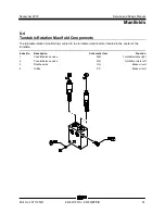
Page 61: ...Components The turntable rotation manifold is mounted to the turntable rotation motor located in the center of the turntable Index No Description Schematic Item Function 1 Counterbalance valve MM Turntable rotate right 2 Counterbalance valve NN Turntable rotate left 3 Shuttle valve OO Brake circuit 4 Orifice PP Brake circuit ...

Page 62: ...t No 1271125GT 8 5 Oscillate Directional Valve Manifold Components The directional valve manifold is mounted inside the drive chassis at the non steer end Index No Description Schematic Item Function Torque 1 Cap Breather 20 25 ft lbs 27 33 Nm 2 Spool valve OA Directional control ...

Page 63: ...fastener hole in the bracket 7 Install the ball joint to the axle and tighten the jam nut 8 Check and make sure the drive chassis is completely level 9 Measure the distance between the drive chassis and non steer axle on both sides from inside of the drive chassis Note If the distance is not equal and the adjustment to the linkage was completed with ground and drive chassis level repeat steps 4 th...

Page 64: ... above specification voltage increases While valves may operate when coil resistance is outside specification maintaining coils within specification will help ensure proper valve function over a wide range of operating temperatures Electrocution burn hazard Contact with electrically charged circuits could result in death or serious injury Remove all rings watches and other jewelry 1 Tag and discon...

Page 65: ...or to a terminal on the coil Resistor 10Ω Genie part number 27287 Note The battery should read 9V DC or more when measured across the terminals 1 multimeter 2 9v DC battery 3 10Ω resistor 4 coil Note Dotted lines in illustration indicate a reversed connection as specified in step 6 3 Set a multimeter to read DC current Note The multimeter when set to read DC current should be capable of reading up...

Page 66: ...level surface 1 Secure the turntable from rotating with the turntable rotation lock pin Note The turntable rotation lock pin is located next to the boom rest pad 2 Tag disconnect and plug the hydraulic hoses from the turntable rotation drive motor Cap the fittings on the drive motor Bodily injury hazard Spraying hydraulic oil can penetrate and burn skin Loosen hydraulic connections very slowly to ...

Page 67: ...h pivot plate to specification Refer to Specifications Machine Torque Specifications 7 Adjust turntable rotation gear backlash Refer to Repair Procedure How to Adjust the Turntable Rotation Gear Backlash How to Adjust the Turntable Rotation Gear Backlash The turntable rotation drive hub is mounted on an adjustable plate that controls the gap between the rotation motor pinion gear and the turntable...

Page 68: ... Readjust if necessary 9 2 How to Replace the Universal Tilt Sensor UTS This machine has a dual axis angle sensing device called the Universal Tilt Sensor UTS It is mounted on the turntable to monitor and communicate ground angle relative to gravity via CAN bus Should the turntable be tilted at the Allowable Tilt Angle or greater an alarm will sound at both the turntable and the platform If not ca...

Page 69: ...rive enable toggle switch and the steer joystick Result The display will show FAULTS 4 Momentarily activate steer in the right direction until SETTINGS is shown on the display 5 Momentarily activate the drive enable toggle switch in the right direction until you see the VALVE AND SENSOR SETTINGS screen 6 Momentarily activate the drive enable toggle switch in the right direction until you see the T...

Page 70: ...ydraulic Hose and Fitting Torque Specifications 1 Rotate the turntable until the boom is between the steer tires or tracks 2 Tag disconnect and plug the oscillating axle cylinder hydraulic hoses Cap the fittings on the oscillate cylinder Bodily injury hazard Spraying hydraulic oil can penetrate and burn skin Loosen hydraulic connections very slowly to allow the oil pressure to dissipate gradually ...

Page 71: ...e machine in the stowed position Refer to Navigation Menus Settings Menu 1 Turn the key switch to platform control 2 Pull out the red Emergency Stop button to the on position at both the ground and platform controls 3 Adjust the steer wheels so they are pointing straight ahead in line with the non steer wheels Release the foot switch 4 Move and hold the drive enable toggle switch in the right dire...

Page 72: ...Service and Repair Manual December 2018 62 Z 60 37 DC Z 60 37 FE Part No 1271125GT This page intentionally left blank ...

Page 73: ...ls chocked All external AC power supply disconnected from the machine Boom in the stowed position Turntable secured with the turntable rotation lock Welder disconnected from the machine if equipped with the weld cable to platform option Before Troubleshooting R Read understand and obey the safety rules and operating instructions in the appropriate operator s manual on your machine R Be sure that a...

Page 74: ...t hour meter will display unit hours and battery state of charge SOC whenever no faults are present on the system The value will cycle between unit hours and battery SOC every 5 seconds When the engine is running if equipped the display will cycle hours SOC and RPM Both Engine Hours and DC Function Enable Hours will be tracked DC Function enable hours will be displayed on the smart hour meter by d...

Page 75: ...ctivate the drive enable toggle switch in the right direction until ACTIVE FAULTS is shown on the display 10 Activate the steer rocker switch in the right direction until FAULT HISTORY is shown on the display 11 Momentarily activate the drive enable toggle switch in the right direction to access the fault history list codes 12 Activate the steer rocker switch in the right direction to scroll throu...

Page 76: ...n on the switch 24V on C48 10 C194INC WH RD when pressing up on the switch B otherwise 19 AUX PUMP TOGGLE SWITCH 11 Shorted to supply Stuck ON on power up AUX functions disabled Verify when activated 24V created by AUX toggle switch TS1 at platform or ground controls they are wired in parallel 24V at C35 11 to RRDCON C28 33 C27AUX RD to 24V when switch is activated 24V across AUX Relay CR3 86 CR3 ...

Page 77: ...ed mV must be between 2600 3400 mV Elevated mV must be between 400 1200 mV 16 Value at 0v 0V 17 Not calibrated Calibration Not Completed 19 Out of Range Reported angle sensor value out outside normal range more than 3 degrees 26 PRIMARY EXTEND VALVE 12 Value too high Open Circuit or Ohms 35 Associated function disabled Check Ohms Verify no open short circuit across TCON C20 3 BK B V07PBE BK 15 Val...

Page 78: ...ue too high Open Circuit or Ohms 35 Associated function disabled Check Ohms Verify no open short circuit across PCON C47 3 BK or C10 1 B C19JSV GR WH 15 Value too low Short or Ohms 15 41 TURNTABLE JOYSTICK 11 Shorted to supply 5V Turntable Rotate disabled Verify 5V at JC7 2 P162PJW OR B at JC7 1 JSGND BR 500 to 4500 mV at JC7 4 PCON C46 12 C165TRS WH RD through joystick motion 16 Value at 0V 0V 17...

Page 79: ...tartup 56 LEFT FRONT DRIVE CONTROLLER 0 No Response No CAN communication Drive disabled Verify 48V on C28 1 C28 11 R181PWR 0V on C28 12 12 99 Curtis Fault Code Refer to Code 59 RIGHT REAR MOTOR CONTROLLER Refer to Code 59 RIGHT REAR MOTOR CONTROLLER Refer to Code 59 RIGHT REAR MOTOR CONTROLLER 57 RIGHT FRONT DRIVE CONTROLLER 0 No Response No CAN communication Drive disabled Verify 48V on C27 1 R18...

Page 80: ...oller Severe Undertemp Cut Drive EM Brake Cycle Power 16 Controller Severe Overtemp Cut Drive EM Brake Cycle Power 17 Severe B Undervoltage None Auto 18 Severe B Overvoltage Cut Drive EM Brake Cycle Power 22 Controller Overtemp Cutback None Auto 23 B Undervoltage Cutback None Auto 24 B Overvoltage Cutback None Auto 25 5V Supply Failure None Auto 26 Digital Out 6 Overcurrent None Auto 27 Digital Ou...

Page 81: ...to 71 OS General Cut Drive EM Brake Cycle Power 72 PDO Timeout None Auto 73 Stall Detected LOS Reduce Drive Cycle Power 77 Supervisor Fault Cut Drive EM Brake Cycle Power 78 Supervisor Incompatible Cut Drive EM Brake Cycle Power 82 Bad Calibrations Cut Drive EM Brake Cycle Power 83 Driver Supply Fault Cut Drive EM Brake Cycle Power 84 Following Error Fault Cut Drive EM Brake Cycle Power 87 Motor C...

Page 82: ...3 STEER ANGLE SENSOR 11 Shorted to supply 12V High speed drive disabled Verify 12V supply Pin A RRDCON C28 25 P198SEN RD in relation to C28 7 RRDCON Sensor Ground 500 4500mV through steer motion at PIN B C28 24 C111LFS OR and has no open short circuit to either pin A or pin C When wheels are straight signal must be between 2200 3400 mV 16 Value at 0V 0V 17 Not calibrated Calibration not completed ...

Page 83: ...mV must be between 3600 4400 mV Elevated mV must be between 600 1400 mV 16 Value at 0v 0V 17 Not calibrated Calibration Not Completed 19 Out of Range Reported angle sensor value out outside normal range more than 3 degrees 67 DRIVE ENABLE TOGGLE SWITCH 11 Shorted to supply Stuck ON on power up Drive disabled Verify 5V VCON C48 4 C66DRE BL when switch is pressed right and 2 5V when pressed left 68 ...

Page 84: ...oaded Too much weight in the platform detected by LS18 All functions disabled Remove weight from platform Verify B at C10 6 C46 7 C175LDS WH BK 24V at C10 7 C9 3 C4 3 C28 14 C171LDS BK WH 21 Fault Voltage on both or none or not 24V 77 VCON LCD DISPLAY Platform controls 13 No response No CAN communication Lift functions disabled Verify 24V supply on C48 1 B at C48 2 60 Ohm resistance across CAN C49...

Page 85: ... High battery voltage error Battery Voltage is too high to charge Check the battery voltage and cable connections Check battery size and condition This error will automatically clear once the condition has been corrected 2 Low battery voltage error detected prior to starting a charge cycle Battery Voltage is too low to charge 3 Charge timeout Charge Timeout caused by battery pack not reaching requ...

Page 86: ...has been corrected 11 Charger is disabled by external command 12 Reverse polarity error Battery is connected the wrong way around Check the battery connections This error will automatically clear once the condition has been corrected 13 Battery does not take current Battery voltage is detected but the charger is unable to charge the battery This can be due to an electrical device connected between...

Page 87: ...Existing SW is left running Contact Product Support 20 No active algorithm selected There is no active charge profile selected Select a charge profile 21 High battery voltage error detected while charging Battery voltage is too high as detected by the algorithm Check the battery voltage and cable connections This error will automatically clear once the condition has been corrected 22 Low battery v...

Page 88: ...r 27 USB overcurrent fault USB hardware overcurrent protection has been tripped Remove and reinsert USB flash drive If condition persists try using a different USB flash drive 28 Charge profile incompatibility USB hardware overcurrent protection has been tripped Update charger software or select a different charging profile 29 CAN Bus error CANbus network error Check the physical CAN connector ele...

Page 89: ... reprogramming failed Re try CANOpen download or re program using the USB 82 LOAD SENSE RECOVERY 21 Fault Overload was tripped and AUX was used to lower the platform while overloaded All functions disabled Enter LCD menu at Platform Navigate to RESET OVERLOAD RECOVERY Enter Enter reset pass code 83 TELEMATICS REMOTE SHUTDOWN 21 Fault Unit shut down via remote telematics command All functions disab...

Page 90: ...ound path to the relay coil unplug oil pressure switch for this test C108SEL WH BK Oil Pressure Switch contacts open to B after engine start C108SEL WH BK Relay CR64 is operable Output of relay CR64 87 is connected to C27 4 LRDCON through C35 1 R108SEL WH BK 96 LOW OIL PRESSURE OR ENGINE OVERTEMP 19 Value out of range Either the over temperature or low oil pressure switch provided a ground to rela...

Page 91: ...rol System Fault Codes Part No 1271125GT Z 60 37 DC Z 60 37 FE 81 Section 5 Navigati on Menus Navigation Menu Top Menus Drive enable switch Drive Joystick Drive enable switch left Drive enable switch right Drive joystick left Drive joystick right ...

Page 92: ...Service and Repair Manual December 2018 Faults Navigation Menu 82 Z 60 37 DC Z 60 37 FE Part No 1271125GT Faults Navigation Menu ...

Page 93: ...December 2018 Service and Repair Manual Options Navigation Menu Part No 1271125GT Z 60 37 DC Z 60 37 FE 83 Options Navigation Menu ...

Page 94: ...Service and Repair Manual December 2018 Settings Navigation Menu 84 Z 60 37 DC Z 60 37 FE Part No 1271125GT Settings Navigation Menu ...

Page 95: ... obey the safety rules and operating instructions in the appropriate operator s manual on your machine R Be sure that all necessary tools and test equipment are available and ready for use About This Section There are two groups of schematics in this section Electrical Schematics Electrocution burn hazard Contact with electrically charged circuits could result in death or serious injury Remove all...

Page 96: ...no terminal T circuits connect at terminal Circuits crossing no connection Quick disconnect terminal Circuit breaker with amperage Key switch Toggle switch DPDT Toggle switch SPDT Pump or Motor Tilt sensor Horn button normally open Emergency stop button normally closed Resistor with ohm value Battery seperator Gauge sending unit Oil temperature switch normally open Coolant temperature switch norma...

Page 97: ...2 position 3 way Differential sensing valve Filter with bypass relief valve Relief valve with pressure setting Priority flow regulator valve Solenoid operated proportional valve Directional valve mechanically activated Flow divider combiner valve Pilot operated 3 position 3 way shuttle valve Solenoid operated 2 position 3 way directional valve Counterbalance valve with pressure and pilot ratio Sol...

Page 98: ...t front AC motor controller C26 DCON Right front AC motor controller C27 DCON Left rear AC motor controller C28 DCON Right rear AC motor controller C29 Telematics C30 Jumper plug LR RR motor controller to ECON C31 Jib select hydraulic manifold C32 Steer sensor extender C33 Function pump motor Generator C34 ECON AC motor Generator controller C35 DC or Engine option C36 Battery status LED C37 Drive ...

Page 99: ...acon F Fuse F1 Battery 325A F2 F3 Glow plugs 30A F5 Spare 15A F8 Charger 40A F18 Work lights 5A F33 Telematics 6A FS1 Foot switch G Gauge G1 Battery Charge Indicator G2 Engine oil pressure G3 Engine coolant temp G4 Engine oil temp G6 Hour meter Item Description H Horn or Alarm H1 Tilt Platform overload H2 Horn H5 Alarm multifunction JC Joystick JC1 Boom proportional joystick secondary boom up down...

Page 100: ...oom extend retract TS14 Motor shift high low TS15 Drive enable TS18 Work light option TS46 Proximity kill option TS47 Inverter option TS51 Auxiliary pump TS52 Model select TS57 Platform rotate TS58 Jib boom up down TS59 Platform level up down TS60 Secondary boom up down TS61 Primary boom up down TS62 Turntable rotate TS63 Primary boom extend retract U Module U3A DCON RR AC motor controller U3B DCO...

Page 101: ... Fuse 3 30A glow plug 3 Circuit breaker 1 15A Engine start Fuel pump 4 Control Relay 64 Engine fault 5 Control Relay 2 Fuel pump 6 Circuit breaker 7 10A Engine RPM 7 Control Relay 1 Engine start 8 Control Relay 15A glow plug 1 9 Fuse 5 15A spare 10Control Relay 15B glow plug 2 11Diode 6A 12Control Relay 4 Engine RPM 13Connector 1 Blue 14Connector 2 Orange ...

Page 102: ...air Manual December 2018 12V DC Charger Wiring DC Option 92 Z 60 37 DC Z 60 37 FE Part No 1271125GT 1 Control Relay 3 24V auxiliary 2 Circuit breaker 4 10A 3 Battery charger 12V 4 To relay AC input box 5 Connector 14 ...

Page 103: ...December 2018 Service and Repair Manual AC Input Wiring DC Option Part No 1271125GT Z 60 37 DC Z 60 37 FE 93 1 AC input wall plug 2 AC input to 48V charger 3 Charger Control IN 4 To 12V charger ...

Page 104: ...Service and Repair Manual December 2018 CAN BUS Wiring Diagram DC Models 94 Z 60 37 DC Z 60 37 FE Part No 1271125GT ...

Page 105: ...h Angle Sensor Legend Part No 1271125GT Z 60 37 DC Z 60 37 FE 95 1 S17 Primary angle sensor 2 LS1 Boom extend limit switch 3 LS18 overload 4 LS3 Drive enable 5 S13 Steer Angle sensor inside steer cylinder 6 S19 Secondary angle sensor inside upper pivot ...

Page 106: ...Service and Repair Manual December 2018 96 Z 60 37 DC Z 60 37 FE Part No 1271125GT This page intentionally left blank ...

Page 107: ...December 2018 Service and Repair Manual 97 Wiring Diagram Options ...

Page 108: ...Service and Repair Manual December 2018 98 Z 60 37 DC Z 60 37 FE Part No 1271125GT Wiring Diagram Options ...

Page 109: ...December 2018 Service and Repair Manual Part No 1271125GT Z 60 37 DC Z 60 37 FE 99 Schematics Options 4WD DC and FE Models ...

Page 110: ...Service and Repair Manual December 2018 100 Schematics Options 4WD DC and FE Models ...

Page 111: ...December 2018 Service and Repair Manual 101 Power Cable Wiring Diagram ...

Page 112: ...Service and Repair Manual December 2018 102 Z 60 37 DC Z 60 37 FE Part No 1271125GT Power Cable Wiring Diagram ...

Page 113: ...December 2018 Service and Repair Manual 103 Hydraulic Schematic DC and FE Models ...

Page 114: ...Service and Repair Manual December 2018 104 Z 60 37 DC Z 60 37 FE Part No 1271125GT Hydraulic Schematic DC FE Models ...

Page 115: ...December 2018 Service and Repair Manual 105 Electrical Schematic DC FE Models ...

Page 116: ...Service and Repair Manual December 2018 106 Z 60 37 DC Z 60 37 FE Part No 1271125GT Electrical Schematic DC FE Models ...

Page 117: ...December 2018 Service and Repair Manual Part No 1271125GT Z 60 37 DC Z 60 37 FE 107 Electrical Schematic DC FE Models ...

Page 118: ...Service and Repair Manual December 2018 108 Electrical Schematic DC FE Models ...

Page 119: ...December 2018 Service and Repair Manual Part No 1271125GT Z 60 37 DC Z 60 37 FE 109 Electrical Schematic DC FE Models ...

Page 120: ...Service and Repair Manual December 2018 110 Electrical Schematic DC FE Models ...

Page 121: ...December 2018 Service and Repair Manual 111 Ground Control Box Terminal Strip Wiring Diagram DC FE Models ...

Page 122: ...Service and Repair Manual December 2018 112 Z 60 37 DC Z 60 37 FE Part No 1271125GT Ground Control Box Terminal Strip Wiring Diagram DC FE Models ...

Page 123: ...December 2018 Service and Repair Manual Part No 1271125GT Z 60 37 DC Z 60 37 FE 113 Platform Control Box Wiring Diagram DC FE Models ...

Page 124: ...Service and Repair Manual December 2018 114 Platform Control Box Wiring Diagram DC FE Models Z 60 37 DC Z 60 37 FE Part No 1271125GT Ser vice and R epair M anual December 2018 ...

Page 125: ......
Reviews: