December 2018
Service and Repair Manual
Turntable Rotation Components
Part No. 1271125GT
Z®-60/37 DC • Z®-60
/37 FE
59
How t o C alibr at e t he Uni vers al Tilt Sens or
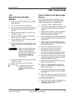
How to Calibrate the Universal Tilt
Sensor (UTS)
Note: Perform this procedure on a firm, level
surface with the machine in the stowed position.
Refer to Navigation Menus,
Settings Menu
.
1
Pull out the red Emergency Stop button to the
on position at both the ground and platform
controls. Turn the key switch to platform
control.
2
Move and hold the drive enable toggle switch
in the right direction while holding steer in the
right direction.
3
When the display leaves SYSTEM READY
mode, release the drive enable toggle switch
and the steer joystick.
Result: The display will show FAULTS.
4
Momentarily activate steer in the right direction
until SETTINGS is shown on the display.
5
Momentarily activate the drive enable toggle
switch in the right direction until you see the
VALVE AND SENSOR SETTINGS screen.
6
Momentarily activate the drive enable toggle
switch in the right direction until you see the
TILT SENSOR CALIBRATE screen.
7
Momentarily activate the drive enable toggle
switch in the right direction to enter the TILT
SENSOR CALIBRATE screen.
8
Momentarily activate the drive enable toggle
switch to save the X and Y axis values.
Result: An audible alarm will sound for one
second indicating a successful calibration.
To exit programming mode:
9
Move and hold the drive enable toggle in the
left position until the display returns to
SYSTEM READY mode.
Summary of Contents for Genie Z-60 DC
Page 54: ...Service and Repair Manual December 2018 Manifolds 44 Z 60 37 DC Z 60 37 FE Part No 1271125GT ...
Page 56: ...Service and Repair Manual December 2018 Manifolds 46 Z 60 37 DC Z 60 37 FE Part No 1271125GT ...
Page 107: ...December 2018 Service and Repair Manual 97 Wiring Diagram Options ...
Page 110: ...Service and Repair Manual December 2018 100 Schematics Options 4WD DC and FE Models ...
Page 111: ...December 2018 Service and Repair Manual 101 Power Cable Wiring Diagram ...
Page 113: ...December 2018 Service and Repair Manual 103 Hydraulic Schematic DC and FE Models ...
Page 115: ...December 2018 Service and Repair Manual 105 Electrical Schematic DC FE Models ...
Page 118: ...Service and Repair Manual December 2018 108 Electrical Schematic DC FE Models ...
Page 120: ...Service and Repair Manual December 2018 110 Electrical Schematic DC FE Models ...
Page 125: ......

