September 2017
Part No. 57.4400.9219
GTH-1256 AF
4-35
Section 4 • Repair Procedures
6-3
Hydrostatic Transmission
Pump
How to Test the Hydrostatic
Transmission Pump
Note: Perform this procedure on a
fi
rm, level
surface, with the boom in the stowed position and
brake pedal engaged.
1 In the proximity of the drive pump, spot the
valve deactivating the drive pump inching.
Once the test is completed, open the valve.
2 Connect a 0 to 8700 psi / 0 to 600 bar pressure
gauge to port TP4 (hydrostatic transmission
high pressure test port).
3 Connect a 0 to 870 psi / 0 to 60 bar pressure
gauge to port TP3 (hydrostatic transmission
boost pressure test port).
4 Start the engine. Shift the transmission into
second gear.
Result: the pressure gauge connected to test
port TP3 reads 406 psi / 28 bar.
Pressure is not within speci
fi
cation.
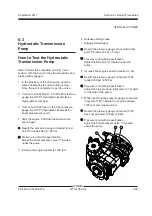
Adjust the boost pressure valve "c" located
under the pump.
5 Increase the engine speed to 1100 rpm.
6 Release parking brake.
7 Engage forward gear.
Result: the pressure gauge connected to test
port TP4 reads 725 psi / 50 bar.
Pressure is not within speci
fi
cation.
Adjust the DA valve "a" located under the
pump.
8 Increase the engine speed to maximum rpm.
Result: the pressure gauge on test port TP4
reads 6450 psi / 450 bar.
Pressure is not within speci
fi
cation.
Adjust the high pressure relief valve "b" located
on the side of the pump.
9 While observing the pressure gauge connected
to test port TP3, operate the engine between
1100 rpm and maximum rpm.
Result: the pressure gauge on test port TP3
does not go below 406 psi / 28 bar.
Pressure is not within speci
fi
cation.
Adjust the boost pressure valve "c" located
under the pump.
a
b
c
HYDRAULIC PUMPS


