Compact Track Loader
19. Service Tool
Control Screens
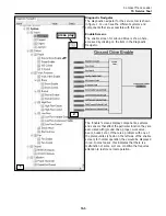
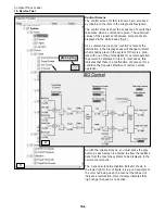
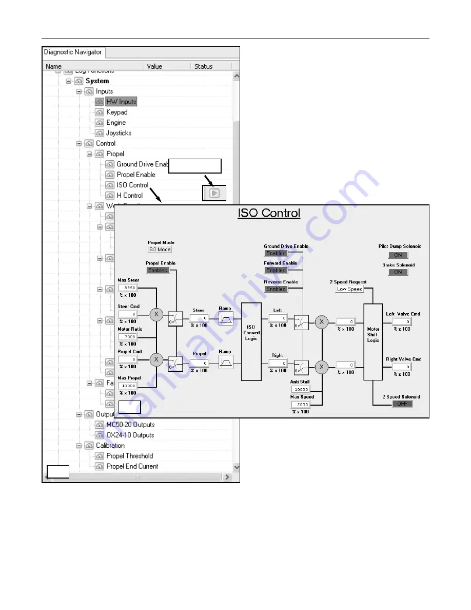
The control screen for ISO is shown here, accessed
by clicking on the item in the Diagnostic Navigator.
The control screens show the sequence of events that
take place when a command is given. The numerical
values of the signals sent between components are
displayed in the white boxes (fig. 4).
As a command is given (ex: joystick is moved) the
information in the display boxes will change to reflect
what is taking place in the system. If there is a prob-
lem with one of the prerequisites for normal operation,
they would be displayed in red. In most cases, this
indicates that there is a malfunction of some sort or a
condition that requires attention to restore normal
operation.
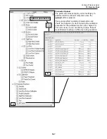
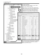
As with the enable screens, you must press the play
button as each screen is entered to allow the realtime
data from the machine systems to be displayed in the
service tool screens.
The 2-speed solenoid activation indicator shown in
the lower right corner of figure 4 is a good example of
the color red being used in a manner that does not
indicate a malfunction. Here it simply indicates that
high range (2-speed) is not active.
19-6
3
4
press play
Summary of Contents for PT100G Forestry
Page 1: ...PT 100G PT 100G Forestry Part Number 2076 286 Printed 8 10 Service Manual Compact Track Loader...
Page 2: ......
Page 6: ......
Page 12: ......
Page 14: ......
Page 22: ......
Page 40: ......
Page 52: ......
Page 62: ......
Page 66: ......
Page 80: ......
Page 98: ......
Page 102: ......
Page 116: ......
Page 136: ......
Page 138: ......
Page 140: ......
Page 141: ......


