5.
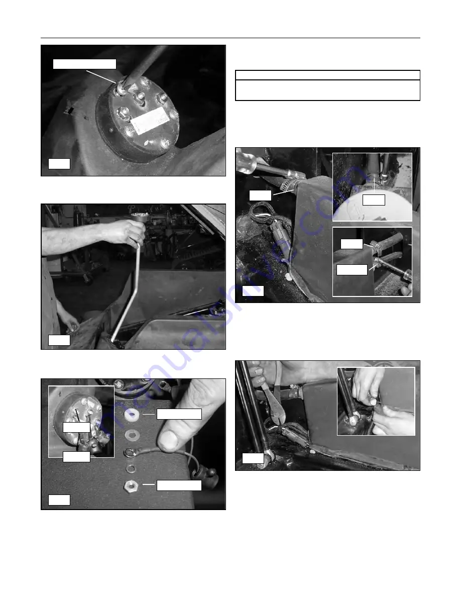
Remove the screws that secure the fuel sending
unit to the tank (fig. 7-2).
6.
Remove the sending unit by pulling it through the
opening in the fuel tank (fig. 7-3).
Installation
1.
To install the fuel sending unit, reverse the removal
procedure (See fig. 7-4 for terminal installation).
Fuel Tank
Removal
1.
Raise and support the lift arms as described on
page 4-1 of this manual.
2.
Tilt and support the operator enclosure (cab) as
described on page 4-2 of this manual.
3.
Loosen the hose clamps that secure the return and
vent hoses to the left and right, rear of the fuel
tank (fig. 7-5).
4.
Disconnect and plug the ends of the hoses to
prevent fuel leakage.
5.
Carefully remove the zip tie from the fuel sending
unit harness and then unplug from the main wire
harness (fig. 7-6).
6.
Loosen the hose clamp securing the main fuel line
to the tank outlet in the front, right corner of the
tank. Disconnect and then plug the line and cap
the outlet to prevent fuel leakage (fig. 7-7).
7-2
Compact Track Loader
7. Chassis and Fuel Tank
7-2
Remove Screws
7-3
7-4
7-5
7-6
Install First
Install Last
-- Neg
+ Pos
Screwdriver
Combination/Socket Wrench
Required Tools
Vent
Vent
Vent
Return
Summary of Contents for PT100G Forestry
Page 1: ...PT 100G PT 100G Forestry Part Number 2076 286 Printed 8 10 Service Manual Compact Track Loader...
Page 2: ......
Page 6: ......
Page 12: ......
Page 14: ......
Page 22: ......
Page 40: ......
Page 52: ......
Page 62: ......
Page 66: ......
Page 80: ......
Page 98: ......
Page 102: ......
Page 116: ......
Page 136: ......
Page 138: ......
Page 140: ......
Page 141: ......


