December 2019
Service and Repair Manual
Hydraulic Pump
Part No. 1285305GT
S
®
-60 J
51
How to Install the Drive Pum p C oupler
How to Install the Drive Pump
Coupler
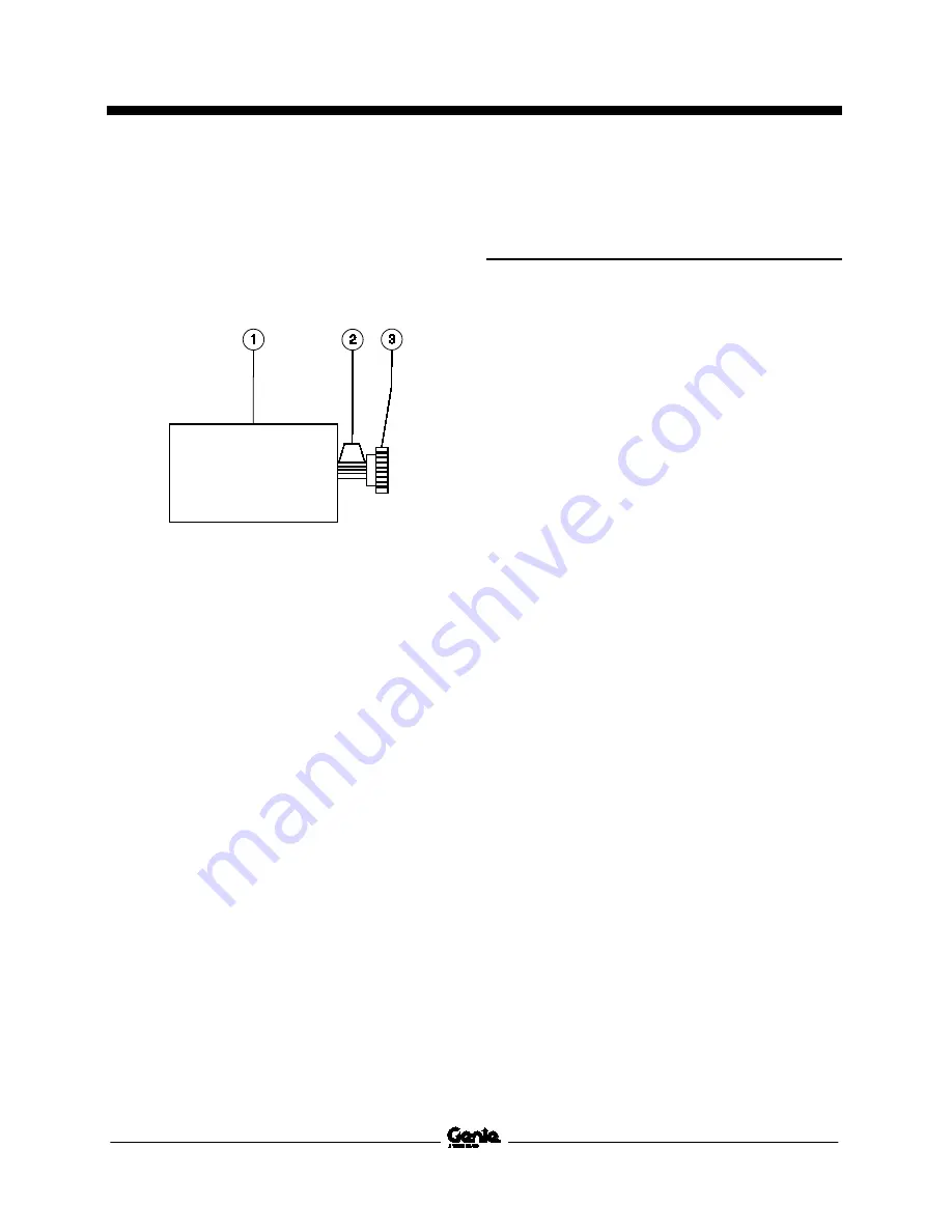
1 Install the coupler onto the pump shaft with the
set screw towards the pump. Leave a
1/32 inch / 0.8 mm gap between the coupler
and pump end plate.
1 drive pump
2 coupler spacing
3 pump coupler
2 Apply Loctite
®
removable thread locker to the
coupler set screw. Torque the set screw to
70 ft-lbs / 95 Nm.
6-3
How to Prime the Drive and
Function Pumps
1 Fill the tank with hydraulic oil until the fluid
level is in the center of the sight glass at the
rear of the tank. Do not overfill.
2 If any of the pumps are new and have not
been previously used, they must be primed.
Drive Pump:
After the pump is installed,
fasteners torqued and all hoses connected,
remove one of the hoses at the top of the
pump (port E or port F) and add a minimum of
0.75 liter / 25 ounces of hydraulic oil to the
pump. Install and torque the hose to
specification.
Function Pump:
After the pump is installed,
fasteners torqued and all hoses connected,
remove the plug at the uppermost port of the
pump and add a minimum of 0.375 liter /
13 ounces of hydraulic oil to the pump. Install
and torque the port plug to 77 Nm / 57 ft-lbs.
3 Locate the quick-disconnect port at the top of
the siphon riser hydraulic oil supply line from
tank to the pumps.
4 Use a clear line to connect an air-powered
vacuum pump to the test port.
5 Activate the pump until no bubbles are seen in
the clear vacuum pump hose while the pump
is running. Disconnect the vacuum pump from
the quick-disconnect port.
6 Start the engine from the ground controls and
check for hydraulic leaks.
Summary of Contents for S-60 J
Page 67: ...December 2019 Service and Repair Manual Manifolds Part No 1285305GT S 60 J 55 ...
Page 69: ...December 2019 Service and Repair Manual Manifolds Part No 1285305GT S 60 J 57 ...
Page 77: ...December 2019 Service and Repair Manual Manifolds Part No 1285305GT S 60 J 65 ...
Page 115: ...December 2019 Service and Repair Manual 103 Electrical Schematic Generator Options ...
Page 118: ...Service and Repair Manual December 2019 106 Electrical Schematic Positive Air Shutdown ...
Page 119: ...December 2019 Service and Repair Manual 107 Electrical Schematic Turntable Controller ...
Page 122: ...Service and Repair Manual December 2019 110 Electrical Schematic Platform Controller ...
Page 123: ...December 2019 Service and Repair Manual 111 Electrical Schematic Kubota D1803 ...
Page 126: ...Service and Repair Manual December 2019 114 Electrical Schematic Kubota D1105 ...
Page 127: ...December 2019 Service and Repair Manual 115 Electrical Schematic Deutz D2011 ...
Page 129: ...December 2019 Service and Repair Manual Part No 1285305GT S 60 J 117 Hydraulic Schematic ...
Page 131: ......


