background image

9-12

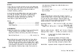
AXLES

Three axles in permanent all-wheel drive with differential
coupling between each axle to prevent driveline wind-up.
Heavy duty axles with fully-floating axle shafts and
outboard planetary gearing.

Automatic limited slip differentials in each axle. Leading
rear axle incorporates a through-drive differential to
transmit drive to the rearmost axle. Locking of this
differential is actuated simultaneously with the
transmission output differential lock.

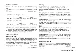
Ratios:

Differential ............................................................... 4.86:1
Planetary .................................................................. 4.94:1
Total Reduction ....................................................... 24.0:1

SUSPENSION

Front: Axle located by a leading A-frame permitting both

vertical movement and oscillation. Rubber cone
suspension medium with heavy duty hydraulic dampers.

Axle Vertical Travel ................................ 105 mm (4.2 in)

Rear: Each axle is coupled to the frame by three rubber-

bushed links with lateral restraint by a transverse link.
Pivoting inter-axle balance beams equalise load on each
rear axle. Suspension movement is cushioned by rubber/
metal laminated compression units between each axle
and underside of balance beam ends. Pivot points on

rear suspension linkages are rubber-bushed and
maintenance-free.

Axle Vertical Travel ............................ ± 115 mm (± 4.5 in)
Axle Oscillation ............................................................ ± 9°

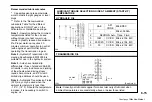
BRAKES

Full hydraulic braking system with enclosed, forced oil-
cooled multiple discs on each wheel. Independent circuits
for front and rear brake systems. Warning lights and
audible alarm indicate low brake system pressure. Brake
system conforms to ISO 3450, SAE J1473.

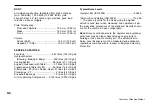
Actuating Pressure ....... 138 ± 6.2 bar (2 000 ± 90 lbf/in²)
Pump Type ................................................ Triple stage gear

Capacity at 2 200 rev/min .... 2.02 litre/s (32 US gal/min)

                                                                                   combined

Braking surface (tractor) .. 802837 mm

2

 (1244.4 in

2

)/brake

Braking surface (trailer) ...... 535225  mm

2

 (829.6 in

2

)/brake

Parking:

Spring-applied, hydraulic-released disc on
rear driveline.

Emergency: Automatic application of driveline brake

should pressure fall in main brake hydraulic
system. Service brakes may also be applied
using the parking-emergency brake control.

Retardation: Hydraulic retarder integral with transmission.

Courtesy of Machine.Market 

Summary of Contents for TA35

Page 1: ...Operation Safety Maintenance TA35 TA40 Courtesy of Machine Market...

Page 2: ...WHENRE ORDERINGTHISHANDBOOK SPECIFY PART NUMBER 15275590 TECHNICALPUBLICATIONSDEPARTMENT TEREX EQUIPMENT LIMITED MOTHERWELL SCOTLAND ML1 5RY Ref No OHE 836 820 June 2005 Courtesy of Machine Market...

Page 3: ...SHOULD BE ALLOWED TO OPERATE THIS VEHICLE The operator is responsible and must be familiar with the contents of the Operator s Handbook and any local regulations prior to operating this vehicle Court...

Page 4: ...Courtesy of Machine Market...

Page 5: ...o the State of California to cause cancer birth defects and other reproductive harm WARNING Battery posts terminals and related accessories contain lead and lead compounds chemicals known to the State...

Page 6: ...used to ensure the operating safety of the machine is not impaired It is only by using genuine parts that the technical requirements stipulated by the manufacturer can be maintained If a General Opera...

Page 7: ...K 98 37 EEC 2000 14 EC UNIT SERIAL NO DATE OF MANUFACTURE INSPECTOR THE ABOVE MACHINERY TAKING INTO ACCOUNT THE STATE OF THE ART COMPLIES WITH OR IS DESIGNED AND CONSTRUCTED AS FAR AS POSSIBLE TO COMP...

Page 8: ...used to ensure the operating safety of the machine is not impaired It is only by using genuine parts that the technical requirements stipulated by the manufacturer can be maintained If a General Opera...

Page 9: ...K 98 37 EEC 2000 14 EC UNIT SERIAL NO DATE OF MANUFACTURE INSPECTOR THE ABOVE MACHINERY TAKING INTO ACCOUNT THE STATE OF THE ART COMPLIES WITH OR IS DESIGNED AND CONSTRUCTED AS FAR AS POSSIBLE TO COMP...

Page 10: ...used to ensure the operating safety of the machine is not impaired It is only by using genuine parts that the technical requirements stipulated by the manufacturer can be maintained If a General Opera...

Page 11: ...o Roading 6 2 In Case Of Trouble 6 4 7 MOVING DISABLED TRUCK Moving Disabled Truck 7 2 8 LUBRICATION AND SERVICING Safety Precautions 8 2 Lubrication and Servicing 8 3 Lubrication and Service Chart 8...

Page 12: ...ator serviceman or other personnel or equipment Report all malfunctions to those responsible for maintenance and do not operate the equipment until corrected Normal service or maintenance performed as...

Page 13: ...ion available at the time of publication The right is reserved to make changes at any time without notice Continuing improvement and advancement of the design may cause changes to your vehicle which m...

Page 14: ...vehicle model code and chassis serial number is found on the unit serial number plate on the rear right of the front frame The vehicle model and serial number should always be referenced in any corre...

Page 15: ...erial number and the serial numbers of all major components and attachments Keep this list up to date and filed in a safe location for fast retrieval Place a decal or notice on the vehicle that all se...

Page 16: ...ents It is helpful to show the investigating officer an Operator s Handbook photographs and advertising to familiarize him with the appearance of the vehicle Report the theft to the insurance company...

Page 17: ...2 1 2 Safety Precautions Courtesy of Machine Market...

Page 18: ...g Be aware of operating hazards that weather changes can create on the job Know proper procedures to follow when a severe rain or electrical storm strikes Never attempt to operate or work on a machine...

Page 19: ...ing object protective structure may be impaired if it has been subjected to any modification or damage Unauthorized modification will void certification Articulation and Oscillation Locks Always conne...

Page 20: ...bumper end of the front chassis and at the rear of the body Note Be aware that this vehicle is free to oscillate if not lifted correctly If in any doubt contact your dealer for further information Veh...

Page 21: ...e starting the engine Don t let greasy oily rags or similar hazards accumulate in the cab If the vehicle has been operated with an under inflated tyre Make sure that the tyre has cooled sufficiently b...

Page 22: ...n all volatile inhibitor fluids and compounds used Follow manufacturer s recommendations when handling and using engine starting fluids and disposing of spent containers Do not puncture or burn empty...

Page 23: ...ric coolant or lubricant heaters are used be sure to follow heater manufacturer s recommendations for use to avoid electrical and or fire hazards Mounting and Dismounting Only use steps and hand holds...

Page 24: ...tarting the vehicle Sound horn before starting the engine or beginning to move the vehicle two blasts for forward and three blasts for reverse Starting Do not start the engine or operate any control i...

Page 25: ...ply pressure a red warning light on the instrument panel will illuminate If this light illuminates indicating a loss of steering power the vehicle must be stopped immediately and no further operation...

Page 26: ...RAL If this occurs stop the vehicle using the service brakes apply the parking brake and do not operate until the fault is corrected Always operate straight up or down slopes whenever possible side hi...

Page 27: ...the road Stay as close to the side of the road as possible Pass other equipment only when the road is clear and enough room and reserve power are available Stop at appropriate intervals to inspect th...

Page 28: ...be used when the body is empty Do not work under or near any unblocked or unsupported linkage part or machine Always install the steering lock bar before making adjustments or servicing the vehicle w...

Page 29: ...kin Always deflate tyre before attempting to remove any embedded objects or removing the tyre and rim assembly from the vehicle Always use a self attaching chuck with a long airline and stand to one s...

Page 30: ...ion should be used for nitrogen inflation Refer to Section 160 0050 Nitrogen Inflation of Tyres of the vehicle Maintenance Manual for recommended procedures for inflating and pressure adjusting tyres...

Page 31: ...sons should stay clear of the vehicle The fire or overheated brakes wheel etc should be extinguished or cooled from a safe distance Do not attempt to extinguish the fire or cool the vehicle by use of...

Page 32: ...dentification 4 ROPS and FOPS Certification Plate 5 Acoustic Foam Precautions 6 Emergency Exit Inside and Outside 7 Pivot Area Precautions 8 Lube Instructions Pivot Pins 9 Vehicle Lifting Hook 10 Vehi...

Page 33: ...older 24 Hydraulic Control Lever 25 Hand Lamp 26 Back Alarm 27 Pre operating Instructions 28 Hydraulic Oil Recommendations 29 Remote Lube and Pressure Points 30 CECertification 31 MachineSerialPlate 3...

Page 34: ...2 18 Courtesy of Machine Market...

Page 35: ...3 1 3 Controls and Operating Courtesy of Machine Market...

Page 36: ...3 2 17 18 19 1 2 3 4 5 37 12 11 10 9 8 7 6 13 14 15 16 23 24 29 32 33 34 28 27 26 25 31 30 22 21 20 1457 Courtesy of Machine Market...

Page 37: ...ol 18 Heater Control 19 Air Conditioner Control 20 Blower Control 21 Retarder Switch TA35 only 22 Body Control Lever 23 Accelerator Control 24 Service Brake Control 25 Recirculation Vents 26 Leg Vents...

Page 38: ...chassis Vehicle should not be moved until this light goes out 5 Tractor Brakes Overstroke Red Illuminates if the brake system pressure is low A buzzer also sounds If light illuminates stop vehicle an...

Page 39: ...ssure Illuminates when the ignition is turned on and should go out when the engine starts If light illuminates stop vehicle and investigate the cause 13 Main Beam Blue Illuminates when headlights are...

Page 40: ...ture Gauge Indicates transmission oil operating temperature This gauge should read in the green zone during normal operation and may read in the yellow zone during use of the retarder If the needle ri...

Page 41: ...dry tank condition which requires bleeding the fuel system 5 Air Cleaner Restriction Gauge Indicates the degree of restriction as the yellow band rises in the gauge window The filter element should be...

Page 42: ...rning Light Test Pressing the switch with the ignition switched on will illuminate the warning lights to provide a bulb and system check Refer to Warning Light section on pages 4 and 5 for details Not...

Page 43: ...osition Unused 12 Diagnostic Request Stop Engine Override Switch Operates as a diagnostic request switch when a the engine is not running and ignition is On b the engine is idling and not in an engine...

Page 44: ...down the engine 1 Ignition switched on instruments gauges and warning lights register as appropriate All electrical systems are operative The key must remain in this position whilst operating the veh...

Page 45: ...am Control Upwards Headlight Flash 2 Direction Indicator Control rearwards Left Indicators Control forwards Right Indicators 3 Windscreen Wiper Washer Position J Not used Position 0 Neutral Position P...

Page 46: ...Conditioner Keep all windows and vents closed Blower control 1 is rotated to select one of three blower speeds The air conditioning will not operate if the blower control is not switched on Temperatur...

Page 47: ...t 6 Backrest height adjustment 7 Damper adjustment 4 positions forward position hardest setting rearmost position softest setting WARNING Do not attempt to adjust seat or seat belt while machine is mo...

Page 48: ...down height and weight adjustment 1 handle and hold until the require height position is achieved release handle bounce lightly until a click is heard the seat position in now engaged properly 5 Pull...

Page 49: ...and held to extract the seat belt 495 WARNING Always wear seat belt when operating the machine Always check condition of seat belts and mounting hardware before operating the machine Anysignsofloosen...

Page 50: ...to hold it stationary Do not FAN the pedal Note TA40 machines have an advanced retarder switch incorporated in the brake pedal For the first 7 of pedal travel the transmission retarder will be applied...

Page 51: ...ied in the gear selected should be high enough to keep the engine operating at governed speed Generally the gear used to ascend a grade is also correct for its descent If the rate of descent is too sl...

Page 52: ...with foot OFF the electronic foot pedal Detroit Diesel Electronic Control DDEC This machine is equipped with the Detroit Diesel Electronic Control DDEC which continually monitors the engine and warns...

Page 53: ...l Module ECM 2 Programmable Read Only Memory PROM 3 Electronic Unit Injectors EUI 4 Batteries 5 Electronic Foot Pedal 6 Check Engine Light 7 Stop Engine Light 8 Diagnostic Request Stop Engine Override...

Page 54: ...into the engine 3 Electronic Unit Injectors EUI The EUI is a lightweight compact unit that injects diesel fuel directly into the combustion chamber The amount of fuel injected and the beginning of inj...

Page 55: ...ponsibility to shut down the engine to avoid serious damage The machine is equipped with the DDEC engine protection system which records the stop engine malfunction in the ECM The stop engine and chec...

Page 56: ...echnician When the engine is not running and the ignition is on or the engine is idling and not in an engine protection condition engine faults can be diagnosed by the operator Pressing and releasing...

Page 57: ...input voltage high 14 175 3 Oil temperature sensor input voltage high 15 52 4 Intercooler coolant temperature sensor input voltage low 15 110 4 Coolant temperature sensor input voltage low 15 175 4 O...

Page 58: ...ltage low 31 51 3 Aux output 3 open circuit high side S3 31 51 4 Aux output 3 short to ground high side S3 31 51 7 Aux output 3 mechanical system fail S3 31 52 3 Aux output 4 open circuit high side T3...

Page 59: ...t temperature high 44 172 0 Air inlet temperature high 44 175 0 Oil temperature high 44 105 0 Intake manifold temperature high 45 100 1 Oil pressure low 45 19 1 High range oil pressure low 46 168 1 EC...

Page 60: ...short to battery W3 62 53 4 Aux output 5 open circuit W3 62 54 3 Aux output 6 short to battery X3 62 54 4 Aux output 6 open circuit X3 62 55 3 Aux output 7 short to battery Y3 62 55 4 Aux output 7 ope...

Page 61: ...8 Turbo speed sensor input failure 64 103 0 Turbo overspeed 65 51 0 Throttle plate position above normal range 65 51 1 Throttle plate position below normal range 65 51 2 Throttle plate position errati...

Page 62: ...5 1 Oxygen content too low 73 151 14 ESS transmission stuck in gear 73 226 11 Transmission neutral switch failure ESS Transmission 73 227 2 Aux analog input data erratic intermittent or incorrect ESS...

Page 63: ...low 82 173 4 Exhaust temperature sensor input voltage low 83 98 0 Oil level high 83 101 0 Crankcase pressure high 83 173 0 Exhaust temperature high 83 173 4 Exhaust temperature sensor input voltage lo...

Page 64: ...ed The machine will stop and hold position when the steering wheel is stopped To return the machine to the straight ahead position or to the opposite direction turn the steering wheel in the opposite...

Page 65: ...odes Ergocontrol table for a list of fault codes and checks on page 3 36 The EST 37 transmission control has been designed to provide the driver with maximum operational flexibility by allowing the ch...

Page 66: ...essing the function button once to resume full automatic mode the function button should be pressed again Manual gears can also be selected by pushing the lever to the left for lower gears or to the r...

Page 67: ...can be used to provide a downshift on demand provided that the vehicle speed is within the range allowable That is the vehicle is not travelling at a speed that would result in the engine overspeedin...

Page 68: ...isplay it can be established which gears are involved and in these circumstances the lower gear should be selected using the shift control lever Automatic mode should be reselected at the earliest opp...

Page 69: ...rive direction and gear before releasing the parking brake Never allow the machine to coast with the transmission in NEUTRAL When running down a gradient the engine speed should not be allowed to drop...

Page 70: ...uring gear shifts 3 1 Drive truck to Substitute mode controlled Electrical problem on speed sensors Check cables and setting of 3 2 next service pressure ramps converter sensors 3 3 lockup clutch dise...

Page 71: ...7 3 7 4 7 5 7 6 7 7 7 8 7 9 8 1 Stop and investigate Limp home Electrical problem on transmission Check cables to transmission 8 2 solenoids control valve 8 3 8 4 8 5 8 6 8 7 8 8 8 9 9 1 Drive truck t...

Page 72: ...Limp home Mechanical or hydraulic problem in Check transmission pressure B 2 clutches or faulty speed reading speed B 3 B 4 B 5 B 6 B 7 B 8 B 9 B A B B B D B E B F C 3 Stop and investigate Normal No...

Page 73: ...s a consequence having a B code See above L F Limp home in forward Shows as a consequence having a 7 8 or B code See above W S Warning sump High oil temperature in sump Reduce engine power and speed W...

Page 74: ...s are actually engaged Note Automatically acting limited slip differentials in each axle will retain traction on most surfaces therefore it should only be necessary to engage the differential locks in...

Page 75: ...remain in this position until the body is to be operated again The control lever should always be kept in FLOAT while the machine is in motion Note The body control lever must remain in the FLOAT posi...

Page 76: ...3 42 Courtesy of Machine Market...

Page 77: ...4 1 4 Operating The Truck Courtesy of Machine Market...

Page 78: ...k for leaks WHEEL PLANETARIES Check for leaks WHEEL PLANETARIES Check for leaks WIRE ROPES Check for debris and damage BRAKE ACCUMULATORS Check for leaks STEERING CYLINDERS Check for debris leaks and...

Page 79: ...should be topped up immediately Note The dash marks on the dipstick are for performing an oil check after the engine is shut down After one or two minutes the level should be up to the top dash mark 3...

Page 80: ...equired 1469 4 5 Hydraulic Filter Check filter indicator and have filter element replaced if necessary 6 Tyres Carefully inspect all tyres for cuts bruises or other damage and proper inflation for the...

Page 81: ...ll Add oil if low 8 Fuel Level Check fuel level gauge Tank should be filled at end of each shift 9 Seat and Seat Belts Adjust the seat position and lap belt as required to allow complete machine contr...

Page 82: ...p Engine light illuminate during operation of the vehicle take effective action to stop the engine and correct the fault as described under DDEC Operation in Section 3 of this handbook WARNING Never s...

Page 83: ...ON position 3 Make sure the body control lever is in the FLOAT position 4 Make sure the transmission gear shift control is in the NEUTRAL position 5 Insert switch key and turn clockwise to position 1...

Page 84: ...overheating 8 7 1142 407 8 The amber Check Engine and red Stop Engine lights should come on and then go out after 6 10 seconds If the amber Check Engine light does not go out have the system checked...

Page 85: ...t be sufficiently reduced to make the method safe Note Be sure vehicles are not touching each other Use cables that are equal to cable size on the vehicle for example 1 0 or 2 0 If jumper cables are u...

Page 86: ...ds 1 Transmission Hot Oil Level Apply the parking brake select neutral gear and start the engine Allow vehicle to idle in neutral for approximately 20 seconds Transmission oil gauge on the dash should...

Page 87: ...ished as per the manufacturers recommendations before carrying out the checks Service Brake Holding Ability Check Depress service brake pedal and move transmission gear shift control to Forward 1st ge...

Page 88: ...ance powertrain effeciencies etc as well as differences in brake holding ability Note As an indication of system deterioration the engine rev min at which point the machine moved with the service or e...

Page 89: ...sure the area around the vehicle is clear of personnel and obstructions before drivingoff In the first few minutes of travel check carefully for the required steering braking engine and transmission p...

Page 90: ...e the service brake as the machine slows until when stopped the pedal is depressed just enough to hold the machine stationary Do not FAN the pedal 7 When the machine has stopped apply the parking emer...

Page 91: ...charger to slow down Shutdowntheengine Note Stoppingaturbochargedengine immediatelyafterhighspeedoperation may cause damage to the turbocharger as it will continue to turn without an oil supply to the...

Page 92: ...t angles to the grade and block wheels securely 3 If below freezing temperatures are expected make sure the cooling system has sufficient antifreeze to prevent the coolant freezing If antifreeze canno...

Page 93: ...5 1 5 Working the Truck Courtesy of Machine Market...

Page 94: ...side using hydraulic excavators or rope shovels Ideally excavators should require 90 or less swing With a backhoe excavator a very efficient loading method is with the backhoe on top of the bank load...

Page 95: ...Waiting machines should stay about two truck lengths behind the one being loaded to avoid any spillage from the loading machine bucket or truck body The operator of the waiting truck is also able to j...

Page 96: ...position of the cleanup machine when entering the loading area to avoid congestion and for maximum safety The following precautions should be observed when approaching the loading area and while bein...

Page 97: ...grade Always remain a safe distance behind the machine ahead particularly on downgrades A good rule of thumb to follow is to allow two 2 truck lengths between machines for each 16 km h 10 mile h of tr...

Page 98: ...R HOPPER is used the operator must avoid rubbing the tyre inner sidewalls When hauling dirt or rock from a borrow pit into a fill area such as an earth fill dam the load is usually dumped in a string...

Page 99: ...ended to prevent unnecessary hydraulic system relief valve operation Never JUMP DUMP the machine by bouncing the rear tyres against a stop block or otherwise jarring the body in its raised position to...

Page 100: ...the truck with the body up No articulated truck is stable in this condition and apart from the risk of a rear end topple there can be severe danger from contacting overhead electric cables trees or b...

Page 101: ...6 1 6 Roading Courtesy of Machine Market...

Page 102: ...ed and in good condition It is also recommended to carry a Warning Triangle The operator must use extra care while on the public highways and remain constantly alert especially for overhead cables and...

Page 103: ...pect for cuts bruises burned beads abnormal wear and damaged wheels rims Replace any damaged or excessively worn tyres Check all hoses drain cocks fuel level check cocks and other potential sources of...

Page 104: ...battery earth cable and apply security locks if so equipped before leaving the parked vehicle Make sure the body is completely lowered and the parking brake is applied Report the following data as soo...

Page 105: ...7 1 7 Moving Disabled Truck Courtesy of Machine Market...

Page 106: ...t ingress of dirt If possible start the engine to provide the required hydraulic pressure for steering and braking If the nature of the trouble prevents engine operation repairs must be made on the si...

Page 107: ...at it is securely locked Note An alternative method of towing a disabled vehicle is by connecting an A Frame arrangement to the lugs on the tractor frame of the disabled vehicle and the towing pin of...

Page 108: ...7 4 Courtesy of Machine Market...

Page 109: ...8 1 8 Lubrication and Servicing Courtesy of Machine Market...

Page 110: ...blocked or unsupported linkage part or machine Always shut down machine according to the procedure under Stopping The Engine described on page 4 15 Turn off the master switch before cleaning lubricati...

Page 111: ...revent dirt from entering the system while servicing Lubricants must be at operating temperature when draining Do not operate any system unless oil level is within the operating range as indicated on...

Page 112: ...34 9 15 26 37 36 7 23 21 14 33 16 32 27 20 22 21 2 21 19 14 20 19 19 20 14 14 19 14 13 13 12 12 22 28 11 10 24 22 3 21 22 21 10 11 29 31 30 21 21 20 19 22 5 4 1 6 38 21 22 19 11 39 39 40 1661 Courtesy...

Page 113: ...to Page 3 Transmission Oil Gauge Check temperature readings General Check for debris leaks and damage 28 Oscillation Bushes Lube 2 EP NLGI See Note 1 12 Suspension Beam Lube 6 EP NLGI See Note 1 and P...

Page 114: ...torque 4 Front 300 Nm 220 lb ft Rear 265 Nm 195 lb ft Engine Crankcase Pressure Check and record 750 5 Hydraulic Oil Filter Clean housing and replace element 1 Engine Air Cleaner Replace element Alter...

Page 115: ...Note 3 Check with the engine idling and the transmission at its normal operating temperature Note 4 When refilling centre axle ensure that 3rd differential unit is primed with 1 litre 1 75 UK pints o...

Page 116: ...ION DAILY Walk Around Inspection Inspect the vehicle as described in Section 4 2 of the Operator s Handbook Engine Visually check engine for damage loose or frayed belts and listen for any unusual noi...

Page 117: ...heck oil level and add oil if low Radiator Check coolant level and add if low Fill the radiator header tank with coolant until coolant reaches the bottom of the filler neck and holds at that level Not...

Page 118: ...hicle particularly the chassis for cracks or broken welds Repair where necessary Service Brakes TA35 Check pads and discs for wear and replace where necessary Test for proper function Note This servic...

Page 119: ...olant tank Replace tank breather Axles TA35 Drain lubricant and refill to level plug Note When refilling centre axle ensure that 3rd differential unit is primed with 1 litre 1 75 UK pints of oil befor...

Page 120: ...einstall suction screens and strainers and refill hydraulic oil tank ENGINES AND TRANSMISSIONS All information contained in the Lubrication and Service Chart was extracted from the relevant manufactur...

Page 121: ...US gal Differential TA40 Extreme Pressure 37 5 litre each MIL L 2105 D GL 5 80W 90 LS Front Gear Lubricant 9 9 US gal See Note 3 Differential TA40 Extreme Pressure 38 litre MIL L 2105 D GL 5 80W 90 L...

Page 122: ...riveshaft through Extreme Pressure 1 50 litre MIL L 2105 D GL 5 80W 90 Bearings Gear Lubricant 0 40 US gal Articulation Extreme Pressure EMS19057 Bearings Lithium Complex AirConditioning Polyalklene G...

Page 123: ...tion bearings Note 1 Operation below the minimum temperatures listed for the oil used without proper preheat or warm up results in greatly reduced transmission life Proper warm up requires 20 minutes...

Page 124: ...8 16 Courtesy of Machine Market...

Page 125: ...9 1 9 Technical Data Courtesy of Machine Market...

Page 126: ...ameter 19 5m 64ft 3 280 10 9 480 1 7 3 340 10 11 3 620 11 7 2 540 8 4 1 600 5 3 3 000 9 10 10 650 34 11 6 500 21 4 5 673 18 5 65 2 170 7 1 2 860 9 4 25 1 540 5 0 1 970 6 6 5 373 17 5 2 530 8 3 1 820 5...

Page 127: ...pled to a 6 speed gearbox with integral output transfer gearing Automatic shifting throughout the range with kickdown feature Lockup in all forward gears A torque proportioning output differential tra...

Page 128: ...equalise load on each rear axle Suspension movement is cushioned by rubber metal laminated compression units between each axle and underside of balance beam ends Pivot points on rear suspension linka...

Page 129: ...ine Pump capacity at 2258 rpm 7 03 litre s 111 US gal min Steering Hydrostatic power steering by two double acting cushioned steering cylinders Actuating pressure for steering operation is supplied by...

Page 130: ...gal Differentials ZF Front Centre Rear 31 litres 8 2 US gal Planetaries ZF 9 litres 2 4 US gal Driveshaft Bearings 1 5 litres 0 4 US gal Air Conditioning Compressor 0 125 litres 0 033 US gal Typical N...

Page 131: ...s Distribution Front Axle 17 700 39 020 Centre Axle 21 350 47 070 RearAxle 21 050 46 405 Gross Weight 60 100 132 495 BareChassis 22 490 49 580 Body 4 950 10 910 Body Hoists pair 660 1 455 Ground Press...

Page 132: ...9 8 Courtesy of Machine Market...

Page 133: ...9 9 TA40 Technical Data On Following Page Courtesy of Machine Market...

Page 134: ...r 19 5m 64ft 3 430 11 3 3 720 12 2 560 1 10 3 450 11 4 3 670 12 0 2 540 8 4 1 600 5 3 3 000 9 10 10 650 34 11 28 6 500 21 4 5 700 18 8 65 2 240 7 4 675 2 3 3 100 10 2 25 1 540 5 0 1 970 6 6 5 370 17 7...

Page 135: ...led to a 6 speed gearbox with integral output transfer gearing Automatic shifting throughout the range with kickdown feature Lockup in all forward gears A torque proportioning output differential tran...

Page 136: ...le Suspension movement is cushioned by rubber metal laminated compression units between each axle and underside of balance beam ends Pivot points on rear suspension linkages are rubber bushed and main...

Page 137: ...mission The components are protected by advanced full flow filtration to 12 micron particle size on the return line Pump capacity at 2258 rpm 7 03 litre s 111 US gal min Steering Hydrostatic power ste...

Page 138: ...ansmission filters dry fill 56 litres 14 8 US gal Differential Dana Front 37 5 litres 9 9 US gal Differential Dana Centre 38 litres 10 US gal Differential Dana Rear 31 5 litres 8 3 US gal Planetaries...

Page 139: ...s Distribution Front Axle 20 170 44 465 Centre Axle 23 530 51 875 Rear Axle 23 530 51 875 Gross Weight 67 230 148 215 Bare Chassis 24 670 54 390 Body 5 400 11 905 Body Hoists pair 660 1 455 Ground Pre...

Page 140: ...9 16 Courtesy of Machine Market...

Page 141: ...10 Symbol Identification Courtesy of Machine Market...

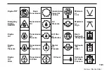
Page 142: ...symbols that may appear on your machine Basic Switch Warning Off Hourmeter Lock Symbol Pressurised Negative Fast Basic Compartment Ground Engine Master Ammeter Slow Engine Switch Starter Switch Circu...

Page 143: ...Oil Pressure or Shut Off High Engine Transmission Air Filter Basic Oil Oil or Hydraulic Pressure Restriction Oil Symbol Engine Transmission Starter Hydraulic Oil Oil Air Oil Pressure Temperature Pres...

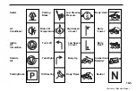
Page 144: ...Light Low Windshield Temperature Or Beam Wiper Fill tube Coolant cold Fuel Filter Light High Windshield Beam Defroster Coolant Hot Fuel Instrument Windshield Shut Off Panel light Washer Cooling Basic...

Page 145: ...sure Air Brake Oil High Speed Body Conditioner Temperature or Level Lower Inside TurnLeft Low Speed Body Air or Level Float Circulation Outside Turn Right BodyUp Dumpertruck Air Retarder ParkingBrake...

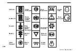
Page 146: ...ension Stop Brake Trans Do Not Lift Applied Maintenance Over speed Clutch Engaged Forward Brake Applied Transmission Clutch Convertor Disengaged Reverse Water in Brake air Fuel Pressure Clutch Wait to...

Page 147: ...10 7 Notes Courtesy of Machine Market...

Page 148: ...10 8 NOTES Courtesy of Machine Market...

Page 149: ...10 9 NOTES Courtesy of Machine Market...

Page 150: ...10 10 NOTES Powered by TCPDF www tcpdf org Courtesy of Machine Market...

Reviews: