background image

Controls and Operating

3-22

Heater

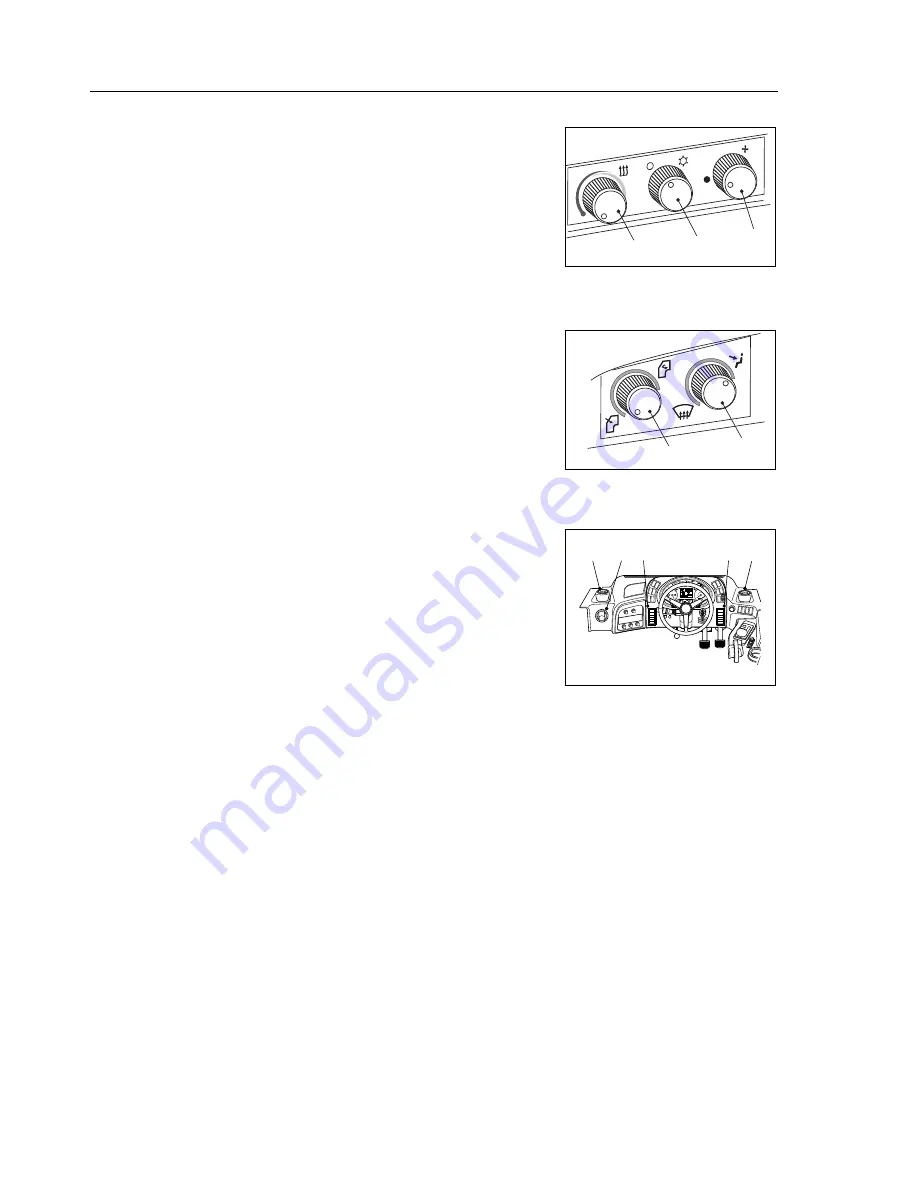
The blower control (3) is rotated to select one of three blower speeds. Air 
direction can be adjusted by turning the direction controls (4 and 5).

The temperature control (1) is rotated to vary the heater output             
temperature. Heater output air is unheated with the control turned fully 
anticlockwise and heated by turning clockwise.

Heater/air conditioner outlets (6) may be adjusted to control the air flow 
output by opening and closing the control flaps. Air direction can be 
adjusted by rotating the complete outlet.

Air Conditioner

Keep all windows and vents closed.

Blower control (3) is rotated to select one of three blower speeds. The air 
conditioning will not operate if the blower control is not switched on. Air 
direction can be adjusted by turning the direction controls (4 and 5).

Turning control (2) to the right switches on the air conditioning. The air 
conditioner output temperature can be controlled using the temperature 
control (1).

The heater/air conditioner outlets (6) may be adjusted to control the air 
flow output by opening and closing the control flaps. Air direction can be 
adjusted by rotating the complete outlet.

NOTICE: 

When the air conditioning is switched on, the engine cooling fan 

automatically engages.

Air Condition Commissioning Procedure

If the machine has been idle overnight or for an extended period of time, 
the refrigerant in the air conditioning unit converts from a gas to a liquid. 
This puts the compressor unit under a great deal of strain trying to      
compress a liquid instead of a gas, and could cause a failure of the air 
conditioning unit.The following commissioning procedure allows the air 
conditioning unit to achieve normal operating parameters.

1. Start the machine and allow it to run until the engine is at a normal 

operating temperature of 80°C (176°F).

2. Turn the blower control to setting 1.
3. Turn on the air conditioning unit on for 5 seconds then off for                

5 seconds.

4. Repeatedly switch the air conditioning on and off for at least 1 minute. 
This should be at least 12 repetitions.
5. Commissioning the air conditioning unit is complete and ready for use.

NOTICE: 

Follow the instructions given above, otherwise the machine may 

be damaged.

1

2

3

3

2

1

1731

1730

4

5

CAN
ERROR
MCU

100%

TC

ERROR
CODE

MCU

88 : 88 : 88

ECU
TCU
OMNIA

999.9

1/h

AUTO

N

CONVERT

P

5

0

10

15

20

25

30

STOP

1

2

RE

AR

0

10

20

30

40

80

70

60

50

0

10

20

50

40

30

km/h

rpm

mph

000000

00_

6

6

6

6

6

MOT00307

Summary of Contents for TA400

Page 1: ...Operations Manual TA400 15504854 OHE11151 TEREX Equipment Limited Operations Manual Original Operating Instructions ...

Page 2: ...This page is intentionally left blank ...

Page 3: ...herwell ML1 5RY Scotland Tel 44 0 1698 732121 Fax 44 0 1698 503210 http constructionsupport terex com www terex com OHE11151 Re order Part Number 15504854 This controlled document is the original instruction and should remain with the vehicle at all times Revision October 2012 Dealer TEREX Equipment Limited Operations Manual Re order ...

Page 4: ...This page is intentionally left blank ...

Page 5: ...n this manual to the best of our knowledge were correct at the time of print The right to change specifications equipment and maintenance instruc tions at any time without notice is reserved as part of the Terex Equip ment Limited policy of continuous development and improvement of the product No part of this publication may be reproduced transmitted in any form electronic mechanical photocopying ...

Page 6: ...This page is intentionally left blank ...

Page 7: ...PETENT PERSONNEL SHOULD BE ALLOWED TO OPERATE THIS VEHICLE The operator is responsible and must be familiar with the contents of the Operations Manual and any Local National regulations prior to operating this vehicle ...

Page 8: ...This page is intentionally left blank ...

Page 9: ...ts are known to the State of California to cause cancer birth defects and other reproductive harm WARNING Battery posts terminals and related accessories contain lead and lead compounds chemicals known to the State of California to cause cancer and reproductive harm Wash hands after handling ...

Page 10: ...This page is intentionally left blank ...

Page 11: ...fice Village Siskin Drive Coventry CV3 4FJ England SIGNATURE DATE UNIT SERIAL NUMBER WE DECLARE THAT THE ABOVE MACHINERY FULFILLS ALL THE RELEVANT PROVISIONS OF THE ABOVE DIRECTIVES CERTIFICATE NUMBER TA400 Articulated Dump Truck INSPECTOR FOR AND ON BEHALF OF THE MANUFACTURER NAME Paul Douglas POSITION General Manager PLACE Motherwell Scotland MANUFACTURER S NAME AND FULL ADDRESS EC DECLARATION O...

Page 12: ...pare parts are used to ensure the operating safety of the machine is not impaired It is only by using genuine parts that the technical requirements stipulated by the manufacturer can be maintained If a General Operating Approval is issued for this machine it may be considered null and void if non genuine parts are used ...

Page 13: ...fice Village Siskin Drive Coventry CV3 4FJ England SIGNATURE DATE UNIT SERIAL NUMBER WE DECLARE THAT THE ABOVE MACHINERY FULFILLS ALL THE RELEVANT PROVISIONS OF THE ABOVE DIRECTIVES CERTIFICATE NUMBER TA400 Articulated Dump Truck INSPECTOR FOR AND ON BEHALF OF THE MANUFACTURER NAME Paul Douglas POSITION General Manager PLACE Motherwell Scotland MANUFACTURER S NAME AND FULL ADDRESS EC DECLARATION O...

Page 14: ...pare parts are used to ensure the operating safety of the machine is not impaired It is only by using genuine parts that the technical requirements stipulated by the manufacturer can be maintained If a General Operating Approval is issued for this machine it may be considered null and void if non genuine parts are used ...

Page 15: ...fice Village Siskin Drive Coventry CV3 4FJ England SIGNATURE DATE UNIT SERIAL NUMBER WE DECLARE THAT THE ABOVE MACHINERY FULFILLS ALL THE RELEVANT PROVISIONS OF THE ABOVE DIRECTIVES CERTIFICATE NUMBER TA400 Articulated Dump Truck INSPECTOR FOR AND ON BEHALF OF THE MANUFACTURER NAME Paul Douglas POSITION General Manager PLACE Motherwell Scotland MANUFACTURER S NAME AND FULL ADDRESS EC DECLARATION O...

Page 16: ...pare parts are used to ensure the operating safety of the machine is not impaired It is only by using genuine parts that the technical requirements stipulated by the manufacturer can be maintained If a General Operating Approval is issued for this machine it may be considered null and void if non genuine parts are used ...

Page 17: ...d Servicing 2 11 Scrapping the Machine 2 12 Mirror and CCTV 2 13 Wheels And Tyres 2 15 Avoid Tyre Explosion Hazard 2 16 Emergency Exit from Cab 2 17 Decals And Instruction Plates 2 18 3 CONTROLS AND OPERATING Controls and Instruments 3 3 Fuse Relay Box 3 4 Basic Data 3 9 Warning Lights and Symbols 3 10 Instruments 3 13 Menu Screen and Buttons 3 14 Switches 3 18 Controls 3 21 Heater 3 22 Air Condit...

Page 18: ...This Page is Intentionally Left Blank ...

Page 19: ...ks 4 10 Brake Function Checks 4 11 Driving And Stopping 4 12 Stopping the Engine 4 14 Parking 4 15 5 WORKING THE MACHINE Working the Machine 5 3 Loading 5 3 Hauling 5 5 Dumping 5 6 Empty Return 5 7 6 ROADING Roading 6 3 General 6 3 Preparation Prior to Roading 6 3 In Case of Trouble 6 4 7 MOVING A DISABLED MACHINE Moving a Disabled Machine 7 3 8 LUBRICATION AND SERVICING Safety 8 3 Lubrications an...

Page 20: ...This Page is Intentionally Left Blank ...

Page 21: ...that all controls are free of mud grease or other matter that might cause slips hazardous to the operator service personnel or equipment Report all malfunctions to those responsible for maintenance and do not operate the equipment until corrected Normal service or maintenance performed as required can prevent unexpected and unnecessary downtime Safety Alert Symbol The Safety Alert System identifie...

Page 22: ...ate injury CAUTION used without the safety alert symbol indicates a potentially hazardous situation which if not avoided may result in property damage INTENDED USE OF MACHINE This product and its approved attachments are designed to perform the following functions 1 Loading 2 Hauling 3 Spreading USE OTHER THAN INTENDED CAUTION Any use other than that stated in Intended use shall be considered impe...

Page 23: ...erate it properly There is a dealer serving every part of the world where these products are sold Your dealer is ready to provide you with any additional information needed and should be consulted for additional publications for this machine When carrying out repairs alterations or fitting attachments it is important that only genuine spare parts are used to ensure the operating safety of the mach...

Page 24: ... Keep machines in well lit areas and ask the local law enforcement authorities to make frequent checks around the storage yard or work site Establish liaison with neighbours and ask them to watch equipment left at job sites and to report any suspicious activities to the local law enforcement authorities Make frequent inventories of machines to promptly detect losses or vandalism Actions to Aid in ...

Page 25: ...Safety 2 1 2 Safety ...

Page 26: ...Safety 2 2 This Page is Intentionally Left Blank ...

Page 27: ...dBlue in the def tank Avoid prolonged or repeated contact with skin After handling always wash hands thoroughly with soap and water In case of contact with eyes rinse immediately with water If large quantities are ingested or irritation persists seek medical attention immediately These machines are equipped with cylinders containing com pressed nitrogen gas Transportation of these machines by any ...

Page 28: ...or signalling Be aware of operating hazards that weather changes can create on the job Know proper procedures to follow when a severe rain or electrical storm strikes Never attempt to operate or work on a machine when not feeling physically fit Know what safety equipment is required and use it Such equipment may be Hard hat safety glasses reflector type vests respirators and ear plugs Never wear l...

Page 29: ... be parked on a level surface wheels blocked steering and oscillation lock bars connected The machine should be lifted using a spreader bar if possible Lift using FOUR slings from the lifting points provided at the bumper end of the front chassis and at the rear of the body NOTICE Be aware that this machine is free to oscillate if not lifted correctly If in any doubt contact your dealer for furthe...

Page 30: ... fluids for cleaning purposes Use approved nonflammable solvents Make sure all fluid system caps drain cocks valves fittings lines etc are secure and leak free Never use an open flame match lighter etc when checking fuel lubricant coolant and battery fluid levels or when checking for fluid leaks Use a flashlight or other safe lighting only Shut off the engine and use extra caution if the engine is...

Page 31: ...idance of sparks at the battery posts Use jumper cables only as recommended Improper use can result in battery explosion or unexpected machine motion Never operate the engine starter for more than 30 seconds and allow two minutes between long cranking periods for cooling An overheated starter could cause a fire If electric coolant or lubricant heaters are used be sure to follow the heater manufact...

Page 32: ...ine motion Always obey Starting the Engine instructions described in Sec tion 4 Do not bypass the machine s neutral start system The neutral start system must be repaired if it malfunctions Start and operate the machine only from the operator s seat Operating Ensure all cab glass mirrors and light lenses are clean during the machine operation for maximum visibility Ensure mirrors are properly set ...

Page 33: ...ear and maintain safe speed with the service brakes or and retarder Always maintain safe speeds for haul road operating conditions for maximum control Reduce speed before turning In the event of a loss of electric power to the gear shift control the transmission will automatically lock in Neutral If this occurs stop the machine using the service brakes apply the Parking Emergency brake Do not oper...

Page 34: ...hine is in gear Always stay in the cab when the machine is being loaded Always lower the body and shut down the machine according to the procedure under Stopping The Engine described in Section 4 before leaving the machine unattended If on a grade wheels should be blocked Roading Match speed to road conditions Yield the right of way when required Obey the rules of the road Stay as close to the sid...

Page 35: ...ll the steering lock bar before making adjustments or servicing the machine with the engine running Refer to General safety section Always shut down the machine according to the procedure under Stopping The Engine described in Section 4 and turn off the master switch before cleaning lubricating or servicing the machine except as called for in this operations manual or the maintenance manual Always...

Page 36: ...used to maintain a stable machine as components are removed and the machines centre of mass changes Fluids must be drained off into suitable containers and if possible recycled otherwise disposed of an environmentally friendly in accordance with local regulations Care must be taken when dealing with flammable liquids and the machine parts that contained those liquids Any process that could ignite ...

Page 37: ...minimize hazards due to restricted visibility Modifications made to the machine may restrict the visibility and compromise compliance with safety standards ISO 5006 2006 Make sure that all mirrors are installed and adjusted to optimize operator visibility The mirrors illustrated below are all capable of adjustment Make sure that the brackets which support these mirrors are folded out from the cab ...

Page 38: ... MUST adjust the mirrors and set the CCTV camera to achieve visibility as identified below Areas 2 8 and 10 can be directly viewed from the operator s seating position without the need for mirrors Adjust mirror A to facilitate the view of Areas 1 2 3 14 and 15 Adjust mirror B such that Areas 4 and 14 are fully visible Adjust mirror C such that Areas 6 and 12 are fully visible Adjust mirror D to fa...

Page 39: ...re used for air inflation should be used for nitrogen inflation Refer to Section 160 0050 Wheel Rim and Tyre of the machine maintenance manual for recommended procedures for inflating and pressure adjusting tyres with dry nitrogen gas Only proper nitrogen charging equipment operated by personnel trained in its use should be used CAUTION Never mix components of one manufacturer s rims with those of...

Page 40: ...achine All other persons should stay clear of the machine The fire or overheated brakes wheel etc should be extinguished or cooled from a safe distance Do not attempt to extinguish the fire or cool the machine by use of hand held fire extinguishers If it is absolutely necessary to approach a machine with a suspect tyre approach only from the front or the back Stay at least 15 m 50 ft from the trea...

Page 41: ...ted on a bracket on the rear wall of the cab and can be easily lifted off in an emergency CAUTION Do not attempt to break the windscreen with the Emergency hammer It is ONLY provided to allow access through the left hand and right hand windows Exercise extreme care when breaking the window glass to protect your face and body from airborne glass particles Be careful when passing through the window ...

Page 42: ...aution Radiator 26 Decal Caution Anti Freeze 27 Decal Caution Cab Tilt 28 Decal Caution Filters 29 Decal Caution Jump Start 30 Decal Notice Nitrogen 31 Decal Caution Power Down 32 Decal Caution Welding 33 Decal Notice Cab Jack 34 Decal Warning Reversing 35 Decal Danger Battery 36 Decal Danger Power Lines 37 Decal Warning Accumulator 38 Decal Warning Fall Hazard 39 Decal Service Panel ISO 40 Serial...

Page 43: ...OT00177 15332852 Hood Raise Lower 1806 PART NO 15370848 MOT00344 Tie Down Point 15370853 MOT00345 Battery Shut Off 15356570 Safety Harness 2222 CE Marking 1799 15321634 Emergency Exit 1804 9361787 Battery Earth 1798 15318464 Steering Column Adjustment 1801 15314811 Body Control 1800 15321641 P P Park Brake 1805 9271069 Hook Point 1797 ...

Page 44: ...16595 TEREX EQUIPMENT LIMITED NEWHOUSE INDUSTRIAL ESTATE MOTHERWELL SCOTLAND ML1 5RY MODEL NO PRODUCT IDENTIFICATION NO MAX RATED PAYLOAD MASS UNLADEN STRUCK CAPACITY ENGINE POWER lb kg lb kg yd m hp kW YEAR OF MANUFACTURE MODELYEAR Serial Plate 1808 MOT00172 Lift Instruction Serial Plate MIN MAX 54 C 65 F 54 C 130 F 29 C 20 F 74 C 165 F 18 C 0 F 82 C 180 F 0 C 32 F 99 C 210 F 7 C 45 F 99 C 210 F ...

Page 45: ...m Articulation Warning Use safety lock 1873 15334756 Crush Hazard Warning Use safety prop 1874 15370753 MOT00347 Crush Hazard Warning Seat Belt 15334765 Entanglement Warning Stop engine before servicing 1879 15334762 Skin Injection Warning Relieve pressure before service Use card to search for leaks 1877 15334764 Read And Understand Operator Manual 1878 15334766 Hot Surface Warning Allow to cool b...

Page 46: ...15334777 Cab Jack Notice 1889 15334774 Welding Notice See the Operations Manual for welding procedures 1888 15334771 Jump Start Notice Jump start using identical battery pack 1885 15334770 Filters Notice See the Operations Manual for replacement intervals 1884 15334769 1 2 Cab Tilt Notice Raise hood before tilting cab 1883 15334767 Burn Hazard allow to cool before opening 1881 15334768 Anti freeze...

Page 47: ... 500 kV 500 750 kV 750 1000 kV d d 10 ft 3m 15 ft 4 6m 20 ft 6 1m 25 ft 7 6m 35 ft 10 7m 45 ft 13 7m Power Lines Warning Maintain required clearance 2171 Emergency Stop Switch Warning should use only in emergency situation 15363060 CAUTION Pressing the emergency stop switch immediately disconnects the battery therefore all electrical power is switched off the engine stops the park brake will be ap...

Page 48: ...k on this machine without safety harness and lanyard 15356708 WARNING Fall Hazard Warning 2220 15333273 Injection Hazard Escaping fluid under pressure can penetrate skin resulting in serious injury Relieve pressure before disconnecting hydraulic lines Keep away from leaks and pin holes Use a piece of cardboard or paper to search for leaks Do not use hand Fluid injected into skin must be surgically...

Page 49: ...turer DANGER Danger Batteries 1983 15333280 NOTICE When tilting cab damage to hood may result Raise hood before tilting cab Cab Tilt Notice 1825 NOTICE 15333288 Cab Jack Notice 1833 15333279 Using incorrect concentration of anti freeze may result in damage See hand book for correct concentration of anti freeze NOTICE Antifreeze Notice 1824 15333276 Entanglement Hazard Rotating parts can result in ...

Page 50: ...losion Hazard Death or serious injury can result from release of pressurised liquids Do not weld or drill into accumulator Keep away from flames Relieve all pressure before performing service on accumulator 15334869 Accumulator Warning 1985 Welding Notice 1830 15333285 NOTICE Welding truck can seriously damage ECUs and components Disconnect the following in order before welding 1 Turn off master s...

Page 51: ... T2 ONLY CHECK OIL LEVEL ADD OIL IF LOW 2 6 16 17 18 19 25 1 1 3 6 2 1 2 EPL LZ EPL EP LI COMP AS REQUIRED AS REQUIRED SEE NOTE 3 4 TRANSMISSION BREATHER DRIVE BELT DIFFERENTIALS WHEEL PLANETARIES ARTICULATION BEARINGS OSCILLATION PIVOT PARKING BRAKE PADS CLEAN IF RQUIRED CHECK TENSION TIGHTEN IF REQUIRED CHECK OIL LEVEL ADD IF LOW CHECK OIL LEVEL ADD IF LOW LUBE CHECK END FLOAT ADJUST IF REQUIRED...

Page 52: ...Safety 2 28 This Page is Intentionally Left Blank ...

Page 53: ...Controls and Operating 3 1 3 Controls and Operating ...

Page 54: ...Controls and Operating 3 2 This Page is Intentionally Left Blank ...

Page 55: ...h 11 Transmission Retarder Request Switch 12 Engine Exhaust Brake Request Switch 13 N A 14 Transmission Differential Lock Request switch 15 Retarder Lever 16 Heated Mirrors Optional 17 Rear Working Lights Optional 18 Flashing Rotating Beacon Optional 19 Rear Fog Lamp Optional 20 Park Emergency Brake Control 21 Heater Vent 22 Transmission Gear Shift Control 23 Body Control Lever 24 Cup Holder 25 Ac...

Page 56: ...Controls and Operating 3 4 FUSE RELAY BOX ...

Page 57: ...Convertor F12 7 5A Telematics Interface F13 15A Work Socket 24V F14 10A Air Seat Compressor F15 5A Hydraulic Oil Sensors F16 20A Fuel Heater F17 20A Engine Management System F18 2A Main Controller F19 15A Main Controller F20 25A Spare F21 20A Engine Management System F22 2A Main Controller Ignition Lock F23 15A Main Controller F24 7 5A Spare F25 2A Programming Interface F26 15A Hood Lift F27 3A Se...

Page 58: ...Light F45 20A Spare F46 10A Not Connected F47 10A Spare F48 2A TCU Diagnostic Interface F49 5A Steering Column Switch F50 7 5A Dashboard F51 1A Transmission Temperature Sensor F52 1A Relay F53 5A Wiper Motors F54 7 5A Transmission Shift Lever F55 5A Foot Switch F56 1A Temperature Sensor F57 2A Transmission Speed Sensor F58 3A Sensors Front Frame F59 10A Front Wiper Motor Speed F60 7 5A Transmissio...

Page 59: ...76 10A Engine Management System F77 10A Ignition Telematics F78 10A Engine Management System F79 15A Main Controller F80 15A Not Connected F81 15A Not Connected F82 15A Not Connected F83 15A Not Connected F84 2A Not Connected F85 2A Not Connected F86 20A Spare F87 20A Not Connected F88 1A Not Connected F89 15A Not Connected F90 2A Not Connected F91 15A Not Connected F92 2A Not Connected F93 5A Eme...

Page 60: ...ay Differential Lock K6 Power relay Front Work Lights K7 Power relay Rear Work Lights K8 Micro Relay Horns K9 Power relay K10 Mini Relay K11 Power relay Emergency Operation K12 Power relay K13 Power relay K14 Micro Relay K15 Micro Relay Wiper Motors K16 Micro Relay Wiper Motors K17 Micro Relay Cabin Up Down ...

Page 61: ... display layout The meaning of all LED Indicators are given in the following pages The dashboard display consists of the following 1 Warning lights and symbols 2 Instruments 3 3 5 color display and buttons CAUTION When removing the Giga Panel above do not use sharp objects to leaver the panel out as this will result in damage Kneel on the cab floor place your hands behind the panel and apply gentl...

Page 62: ... serious damage NOTICE The fault code is displayed in the Diagnostic Screen 4 Engine Check Light When the Check Engine light comes on the ECU has detected a fault in the engine The fault should be diagnosed and corrected at the earliest opportunity 5 Engine Exhaust Brake Indicates that the engine exhaust brake has been requested and is active It remains active until the brake is deactivated 6 Diff...

Page 63: ...ear brake system accumulator A buzzer also sounds If the light illuminates stop the machine and investigate the cause 5 Body UP Indicator Lamp Indicates that the body has been raised and it is off the chassis bed Transmission upshift is restricted while the light is illuminated 6 Front Brakes Accumulator Pressure low Illuminates to warn of low pressure in the front brake system accumulator A buzze...

Page 64: ...tched on 2 Direction Indicators Flashes when the indicator lights left or right are operating NOTICE The indicator flash is accompanied with buzzing signal 3 Lights ON Is ON if the control stock switch is set to headlights ON or working lights ON Warning lights and symbols Below 2 MOT00085 3 1 Control Stock Switch P MOT00093 ...

Page 65: ...il Temperature Gauge Indicates hydraulic oil operating temperature The gauge should read in the white zone during normal operation Should the temperature increase above 80 Deg a warning light 4a on the instrument display will illuminate If the gauge reads in the red zone stop the machine and investigate the cause 5 Transmission Oil Temperature Gauge Indicates transmission oil operating temperature...

Page 66: ...The Dashboard display screen provides a 320 x 240 pixel color display used as a flexible operator information device There are several different screens displayed during power up normal operation body lift brightness and date time setup and engine and transmission diagnostics 3 Right Menu Control Button Switching between the different screens is performed automatically depending on the current act...

Page 67: ...gated 6 Front Windscreen Wiper Intermediate Status Bar Displays the speed stage at which the wiper is operating The front windscreen wiper intermediate Status Bar is shown just as the control stock wiper switch is set to Intermediate position The intermediate sta tus can be set from step 1 slow 15 sec pause time to step 6 fast 0 sec pause time by using the Display Menu Switch 7 MCU Error Code Refe...

Page 68: ... Up Indicates that the body has been raised and it is off the chassis bed Transmission upshift vehicle movement is restricted while the light is illuminated The Body Up Counter is incremented after each regular body up down cycle A few seconds after the body proximity switch signal has changed from Body is UP to Body is DOWN position the display returns to the main screen Whenever the body up scre...

Page 69: ...y pressing Right Menu Control Button for 2 seconds Screen 5 ECU TCU Diagnostic Screen The Diagnostic Screen shows the current Fault Status of the engine and the transmission ENGINE DIAGNOSTICS is based on the Message sent by the ECU via CAN The ECU sends not more than 10 Fault Codes and the status of the amber warning lamp the light comes on when the ECU has detected a fault in the engine and the ...

Page 70: ...the Left Menu Control Button is to be used to change values brightness setup setting date time etc of the menu screen or to be used as ENTER OK Button in particular situations This switch is also used to switch off the buzzer by keeping it pressed for 4 seconds when the engine is not running 4 Display Menu Navigation Switch Switching between the different screens is performed using this switch 5 N...

Page 71: ...he transmission retarder when service brake is applied Position C Transmission retarder request ON This position applies the transmission retarder when throttle pedal is not active 11 Drop Box HI LO Switch Pressing the bottom of the switch engages the low gear ratio in the drop box With the switch in the off position the drop box defaults to the high ratio NOTICE It is only possible to select rati...

Page 72: ...top After a few seconds the buzzer alarm sounds to indicate that the power is still ON On switching the key from 1 to 0 the power goes off The engine will go to low idle and after 3 seconds the engine will stop 18 Diagnostic Test Point Test points are located at the right hand side of the cabin This comprises a 4 plug in connector for 1 X36 CAN 4 Diagnostic Bus For special Diagnostic Equipment 2 X...

Page 73: ...hts ON High Beam Flash is possible in any position 2 Direction Indicator Control Rearwards Left Indicators Control Forwards Right Indicators 3 Windscreen Wiper Washer Position 0 Neutral Position Position 1 Intermittent Sweep Position 2 Wiper Fast Speed Position 3 Windscreen Wash 4 Headlight Parking and Front Working Lights Position 0 Light OFF Position 1 Parking Light and Headlight ON Position 2 H...

Page 74: ...justed by rotating the complete outlet NOTICE When the air conditioning is switched on the engine cooling fan automatically engages Air Condition Commissioning Procedure If the machine has been idle overnight or for an extended period of time the refrigerant in the air conditioning unit converts from a gas to a liquid This puts the compressor unit under a great deal of strain trying to compress a ...

Page 75: ...stment slide rails 3 Adjustable damper 4 Seat belt 5 Backrest angle adjustment 6 Headrest height adjustment 7 Fore Aft isolator forward position unlocked rearmost position locked 8 Seat cushion fore aft adjustment 9 Seat cushion angle adjustment 10 Lumber support adjustment 11 Arm rest adjustment x2 CAUTION Do not attempt to adjust the seat or seat belt while the machine is moving Loss of control ...

Page 76: ...position is achieved 4 Pull up the depth adjustment handle 7 to facilitate movement of the seat forwards or backwards Release the handle when the required position is achieved 5 If adjustment of the armrest angles is desired this can be achieved by turning the rotary adjusters 10 If the armrests are not required they can be folded up out of the way This is achieved by removing the caps 11 on each ...

Page 77: ...aft isolator 3 position to suit the driving conditions When active shock impacts in the driving direction can be more readily absorbed by the driver s seat Forward position off rearmost position on 10 If necessary carry out fore aft seat adjustments by first lifting the lever 2 moving to the required position then lowering the lever again until it locks It should not be possible to move the driver...

Page 78: ...st once every three years regardless of appearance Stop the machine apply park brakes then carry out adjustments Trainer Instructor Seat The trainer instructor seat has only to be used when operator training or instruction is being performed or for service personnel performing service diagnostics NOTICE The Trainer instructor seat is NOT for continuous passenger use To access the compartment below...

Page 79: ...ons to slow or stop the machine Release the pedal as the machine slows until when stopped the pedal is depressed just enough to hold it stationary Do not FAN the pedal NOTICE Pedal movement will be experienced when applying or releas ing the park emergency brake control when the engine is running Park Brake Pushing the control in will apply the spring operated driveline mounted parking brake and t...

Page 80: ...cooling the machine downgrade speed retarder applied gear range should be manually selected and should be high enough to keep the engine operating at governed speed Generally the gear used to ascend a grade fully laden is also correct for its descent If the rate of descent is too fast the engine brake should be applied which will allow a safe descent and efficient retarder operation If further bra...

Page 81: ...d gear selection per grade specification The engine exhaust brake can now be selected and the acceleration released off gas If the rate of descent is too slow the trans mission should be upshifted to the next highest gear If the rate of descent is too fast the service brakes should be applied and the transmission shifted into a lower gear which will allow a safe descent and efficient engine exhaus...

Page 82: ...e operator when a problem develops The system also takes action to prevent damage to the engine and provides the serviceman with diagnostic capabilities so that problems can be corrected quickly and easily NOTICE Before any welding is done on a machine equipped with the PDE System disconnect the following in this order Battery earth cable battery supply cable alternator earth cables alternator sup...

Page 83: ... combustion chamber The amount of fuel injected and the beginning of injection timing is determined by the engine control unit NOTICE Never apply 12 or 24 volts directly to the terminals on the injectors or engine sensors as they will burn out Before removing injectors the fuel passages must be blown out to prevent fuel flow from entering the cylinder head P STOP X14 X4 X36 X35 X34 S25 X44 5 3 7 4...

Page 84: ...s not running Use SDP3 to de pressurize the system before working on the components Always wear safety glasses when working on the system NOTICE Never apply 12 or 24 volts directly to terminals on the injector or engine sensors as they will burn out Before removing injectors the fuel passages must be blown out to prevent fuel flow from entering the cylinder head The machine is equipped with an eng...

Page 85: ... will store this information in its memory If the malfunction is intermittent the lights will come on and go off as the computer senses the changing engine condition The fault codes are displayed in the diagnostic screen NOTICE Refer to Electronic Fuel System Diagnostic Codes table for fault code descriptions MOT0007 ...

Page 86: ...heating 1 Data valid but below normal operational range that is engine oil pressure too low 2 Data erratic intermittent or incorrect 3 Voltage above normal or shorted high 4 Voltage below normal or shorted low 5 Current below normal or open circuit 6 Current above normal or grounded circuit 7 Mechanical system not responding properly 8 Abnormal frequency pulse width or pending 9 Abnormal update ra...

Page 87: ... air pressure of the atmosphere 2 3 4 110 Engine Coolant Temperature Temperature of liquid found in the engine cooling system 0 1 2 3 4 111 Engine Coolant Level Ratio of volume of liquid found in the engine cooling system to total cooling system volume 1 3 4 156 Engine Injector Timing Rail 1 Pressure The gauge pressure of fuel in the timing rail delivered from the supply pump to the injector timin...

Page 88: ...le under the heading Failure Mode Identifiers SPN SPN Name SPN Description FMIa 2797 Engine Injector Group 1 A first collection of fuel injector circuits that are grouped together 2 3 4 2798 Engine Injector Group 2 A second collection of fuel injector circuits that are grouped together 2 3 4 ...

Page 89: ...ghts_ON 15 MCU OUT_02 X1 16 SHORT E5_LowBeam_Left_ON 16 MCU OUT_02 X1 16 BREAK E5_LowBeam_Left_ON 17 MCU OUT_03 X1 15 SHORT E5_Indicators_LEFT_ON 18 MCU OUT_03 X1 15 BREAK E5_Indicators_LEFT_ON 19 MCU OUT_04 X1 14 SHORT E7_BrakeLights_ON 20 MCU OUT_04 X1 14 BREAK E7_BrakeLights_ON 21 MCU OUT_05 X1 13 SHORT K15_FrontWiper_Speed_1_ON 22 MCU OUT_05 X1 13 BREAK K15_FrontWiper_Speed_1_ON 23 MCU OUT_06 ...

Page 90: ...Front_ON 39 MCU OUT_14 X1 8 SHORT Q29_MidAxleDifflock_engage 40 MCU OUT_14 X1 8 BREAK Q29_MidAxleDifflock_engage 41 MCU OUT_15 X1 9 SHORT Q2_LowIdle_LS_Pressure_reduce 42 MCU OUT_15 X1 9 BREAK Q2_LowIdle_LS_Pressure_reduce 43 MCU OUT_00E X2 18 SHORT TCU_Range_inhibit 44 MCU OUT_00E X2 18 BREAK TCU_Range_inhibit 45 MCU OUT_01E X2 17 SHORT M2_WashPump_Front_ON 46 MCU OUT_01E X2 17 BREAK M2_WashPump_...

Page 91: ... 5 SHORT E9_FogLamp_ON 66 MCU OUT 11E X2 5 BREAK E9_FogLamp_ON 67 MCU OUT 12E X2 6 SHORT M7_BrakeOilCoolerAxialFan_PMW 68 MCU OUT 12E X2 6 BREAK M7_BrakeOilCoolerAxialFan_PMW 69 MCU OUT 13E X2 7 SHORT Q11_EngineFan_speed 70 MCU OUT 13E X2 7 BREAK Q11_EngineFan_speed 71 MCU OUT 14E X2 8 SHORT Q8_BodyRaiseValve 72 MCU OUT 14E X2 8 BREAK Q8_BodyRaiseValve 73 MCU OUT 15E X2 9 SHORT Q8_BodyLowerValve 7...

Page 92: ...AK Not Available 95 MCU OUT 26E X2 44 SHORT Not Available 96 MCU OUT 26E X2 44 BREAK Not Available 97 MCU OUT 27E X2 45 SHORT Not Available 98 MCU OUT 27E X2 45 BREAK Not Available 99 MCU OUT 28E X2 46 SHORT Not Available 100 MCU OUT 28E X2 46 BREAK Not Available 101 MCU OUT 29E X2 47 SHORT Not Available 102 MCU OUT 29E X2 47 BREAK Not Available 103 MCU OUT 30E X2 48 SHORT Not Available 104 MCU OU...

Page 93: ...2 22 S24 BodyRaise Lower High Volt 113 MCU IN_X2 22 S24 BodyRaise Lower Low Volt 114 MCU_Input_11_E BREAK B29_BrakeOilTemp 115 MCU_Input_11_E SHORT B29_BrakeOilTemp 116 MCU_Input_03_E BREAK B12 DroBxOilPresSensor 117 MCU_Input_03_E SHORT B12 DroBxOilPresSensor 118 GIGA PIN XJ 18 GIGA PIN XK 12 GIGA PIN XK 13 S14 TransRetSelSwitch Activated ...

Page 94: ...es 4500 transmission with 4th GEN control has been designed to provide the driver with maximum operational flexibility by allowing the choice of automatic or manual gear selection to optimize vehicle performance under all operating conditions The transmission provides six forward gears one reverse gear and a neutral position The gear positions are indicated by the LCD display on the gearshift leve...

Page 95: ...ine is slowed by use of the service brakes and or retarder When shifting from neutral to start from a standstill or to reverse direction decelerate the engine to idle speed To move forward select Drive D and accelerate the engine to the machine load and speed requirements The transmission will automatically upshift from 1st through 6th ranges as travel speed increases With the throttle fully depre...

Page 96: ...on the gear shift lever A 2 minute countdown begins when the following conditions of the vehicle systems are met 1 Engine at idle 2 Oil is at operating temperature within range 82 104 C 140 220 F 3 Transmission is in Neutral N 4 Transmission output shaft is stationary The oil level will be displayed at the end of the 2 minute countdown During the countdown the display flashes out a numerical value...

Page 97: ... d1 Code list position d1 newest d5 oldest P 27 14 Code repeats until the next code d2 is accessed by pressing the mode button Clearing Diagnostic Codes To clear active codes press and hold mode button for 3 to 5 seconds To clear inactive codes press and hold mode button for 8 to 10 seconds Exiting Diagnostic Mode Any of the following methods may be used to exit the diagnostic display mode Momenta...

Page 98: ...ly Voltage 1 HSD1 High P0701 Transmission Control System Performance P0702 Transmission Control System Electrical Trans ID P0703 Brake Switch Circuit Malfunction P0708 Transmission Range Sensor Circuit High Input P070C Transmission Fluid Level Sensor Circuit Low Input P070D Transmission Fluid Level Sensor Circuit High Input P0711 Transmission Fluid Temp Sensor Circuit Performance P0712 Transmissio...

Page 99: ...nce P0882 TCM Power Input Signal Low P0883 TCM Power Input Signal High P0894 Transmission Component Slipping P0960 Pressure Control Solenoid Main Mod Control Circuit Open P0962 Pressure Control Solenoid Main Mod Control Circuit Low P0963 Pressure Control Solenoid Main Mod Control Circuit High P0964 Pressure Control Solenoid 2 PCS2 Control Circuit Open P0966 Pressure Control Solenoid 2 PCS2 Control...

Page 100: ...l Solenoid 4 PCS4 Stuck On P2718 Pressure Control Solenoid 4 PCS4 Control Circuit Open P2720 Pressure Control Solenoid 4 PCS4 Control Circuit Low P2721 Pressure Control Solenoid 4 PCS4 Control Circuit High P2723 Pressure Control Solenoid 1 PCS1 Stuck Off P2724 Pressure Control Solenoid 1 PCS1 Stuck On P2727 Pressure Control Solenoid 1 PCS1 Control Circuit Open P2729 Pressure Control Solenoid 1 PCS...

Page 101: ...6 Control Circuit High U0001 Hi Speed CAN Bus Reset Counter Overrun IESCAN U0010 CAN BUS Reset Counter Overrun U0100 Lost Communications with ECM PCM J1587 U0103 Lost Communication With Gear Shift Module Shift Selector 1 U0115 Lost Communication With ECM U0291 Lost Communication With Gear Shift Module Shift Selector 2 U0304 Incompatible Gear Shift Module 1 Shift Selector ID U0333 Incompatible Gear...

Page 102: ...less than 750 5 Press the bottom of the low ratio request switch 6 Low ratio will be activated 7 Release the service brake pedal 8 The park emergency brake will automatically disengage when the drive is selected To return to high ratio use the same procedure except on step 5 press the top of the low ratio request switch High Ratio Used where high speed is required Low Ratio Should only be used in ...

Page 103: ... default automatic mode is ON To apply the differential locks slow the machine with the service brakes and operate the differential lock switch s Stop the machine and disengage the differential locks as soon as conditions allow NOTICE It should only be necessary to engage the differential locks in extreme conditions NOTICE Before driving in soft or slippery conditions stop and engage differential ...

Page 104: ...e operator when a problem develops and helps to diagnose errors There are two LEDs on the MCU The top LED illuminates green when indicating power on and the bottom LED flashes either red or yellow depending on status If there are no errors the bottom LED flashes yellow to indicate normal status If either LED flashes red this indicates an error has occurred The rate of flashing gives an immediate d...

Page 105: ...required radius of turn The machine will turn only as the steering wheel is turned and at a rate of turning directly proportional to steering wheel speed The machine will stop and hold position when the steering wheel is stopped To return the machine to the straight ahead position or to the opposite direction turn the steering wheel in the opposite direction CAUTION Do not attempt to adjust the st...

Page 106: ...ion The body should be fully lowered and in the neutral position while the machine is in motion The lever will remain in the neutral position when released Power Down Pushing the lever forward provides hydraulic force to power down the body Pushing the lever fully forward will engage the electric detent When the body reaches the proximity switch the lever springs back to the neutral position and p...

Page 107: ...til the cab is fully tilted and hold in place with cab prop 2 and install the cab prop retaining pin 3 To lower the cab ensure the weight of cab is off the safety prop remove the cab prop and slowly open the valve on the hand pump to gently lower the cab until holes in the cab line up with holes in the mounts Reinstall the 4 cab mounting bolts CAUTION Do not work under or near an operator s cab th...

Page 108: ...the battery box below the battery master switch It is a three position switch Centre off Up raise Down lower Operating the hood control switch will send an electrical signal to the motor fitted to the actuator As the motor is powered the actuator extends outwards to raise the hood or retracts inwards to lower the hood NOTICE Do not lower the hood when the cab is tilted MOT00328 ...

Page 109: ...Operating the Machine 4 1 4 Operating the Machine ...

Page 110: ...Operating the Machine 4 2 This Page is Intentionally Left Blank ...

Page 111: ...lant level when cold Partially unscrew the radiator cap to slowly release pressure before removing the cap completely Fill to the bottom of the filler neck NOTICE In subfreezing temperatures be sure that the coolant contains sufficient antifreeze NOTICE Please refer to the maintenance manual for correct procedure RADIATOR HEADER TANK Check coolant level Check for leaks WHEEL PLANETARIES Check for ...

Page 112: ...w in the sight gauge 6a Add oil if low through tank filler cap 6b Check the filter restriction indicator gauge with the oil at operating temperature If the needle is in the green section of the gauge the filter condition is acceptable If the needle is in the red section the differential pressure across the filter has exceeded 1 2 bar and the filter element must be renewed It is not unusual for the...

Page 113: ... to the recommended pressure while cold 9 Check Fuel Level Gauge The fuel tank should be filled at the end of each shift 10 Seat and Seat Belts Adjust the seat position as required to allow complete machine control at all times with minimum fatigue Make sure the seat belt does not restrict movement for machine operation 041 8 0 0 000 88 88 88 MOT00097 9 1754 10 ...

Page 114: ... before operating at full speed and full load Operate the engine at top rated speed when maximum power is needed for the load NEVER idle the engine for more than 5 minutes at a time shut it off If any gauge operates out of its normal operating range or a warning light illuminates shut the engine down immediately and report to service or maintenance per sonnel NOTICE Operating the engine beyond hig...

Page 115: ...e the body control lever is in the NEUTRAL position 4 Make sure the transmission gear shift control is in the NEUTRAL position 5 Insert the key into ignition switch Turn the key fully clockwise until it stops Wait until all the gauges and warning lights on the dashboard display have completed self check procedure The audible warning buzzer will also sound NOTICE Ensure engine and transmission chec...

Page 116: ...Stop switch to start the engine First the horn will sound and then the engine starts CAUTION Never crank the engine more than 30 seconds continuously Allow starter at least 2 minutes cooling time between long cranking periods to avoid overheating 7 MOT00113 ...

Page 117: ...angerously high and cannot be sufficiently reduced to make the method safe CAUTION Ensure that machines are not touching each other Use cables that are equal to cable size on the machine A booster battery should be the same specification as a discharged battery If jumper cables are used to start an engine be sure to follow this procedure Connect one end of a jumper cable usually colored red to the...

Page 118: ...Hot Oil Level The parking brake must be applied and the machine s wheels securely blocked while carrying out this check With the engine idling transmission in NEUTRAL and at normal operating temperature 80 C 176 F the oil level should be up to but not over the upper mark on the dipstick Add oil if oil is close to or below the minimum oil level 2 Mirrors Ensure mirrors are positioned correctly to m...

Page 119: ...AL so that the parking brake is applied automatically before releasing the service brake pedal Emergency Brake Holding Ability Check Push the parking emergency brake control in to apply EMERGENCY brakes and move the transmission gear shift to Drive Depress accelerator control and accelerate the engine to 1 350 rev min The machine should not move Decelerate the engine move the gear shift control to...

Page 120: ...ring braking engine and transmission power response for maximum operating safety 1 Make sure the body is fully down and the body control lever is in the NEUTRAL position 2 Apply the service brake and release the parking brake switch 3 Select the driving direction and the required gear 4 Sound the horn two blasts for forward and three blasts for reverse 5 Release the service brake apply the acceler...

Page 121: ... to stop the machine in an emergency NOTICE The park brake must be inspected after a severe service park emergency braking stop WARNING There is no mechanical connection between the engine and wheels on machines with converter transmissions The parking brake must always be applied when the engine is switched off NOTICE This machine is installed with a safety feature which prevents uncontrolled mov...

Page 122: ...s allows the engine to cool and the turbocharger to slow down 4 Make sure the body control lever is in NEUTRAL 5 To stop the engine press and release the Start Stop switch 6 Await the dashboard display to re illuminate reboot 7 Turn the ignition key switch to the O position and remove 8 Exit the driver s cabin via egress Turn the master switch OFF This prevents battery draining 9 Turn the master s...

Page 123: ...on a grade position the machine at right angles to the grade and block wheels securely Lock the doors 3 If below freezing temperatures are expected make sure the cooling system has sufficient antifreeze to prevent the coolant freezing If antifreeze cannot be added to the cooling system drain the system completely Check all tyres hoses wiring tubing and fittings for cuts ply separation abrasion fra...

Page 124: ...Operating the Machine 4 16 This Page is Intentionally Left Blank ...

Page 125: ...Working the Machine 5 1 5 Working the Machine ...

Page 126: ...Working the Machine 5 2 This Page is Intentionally Left Blank ...

Page 127: ...aulic excavators or rope shovels Ideally excavators should require 90 or less swing With a backhoe excavator a very efficient loading method is with the backhoe on top of the bank loading over the rear of the truck at the base of the bank Backhoe slew angles can be small leading to very short cycle times For maximum material movement the truck operator must help the loading machine operator to kee...

Page 128: ...tor A cleanup dozer or small loader is often worked in conjunction with the main loading machine to keep the area clear of bucket spillage for maximum efficiency of the loading operation The machine operator must always be alert to the position of the cleanup machine when entering the loading area to avoid congestion and for maximum safety When the loader operator signals that the machine is loade...

Page 129: ...ascending is also correct for descending a grade Always remain a safe distance behind the machine ahead particularly on downgrades A good rule of thumb to follow is to allow two truck lengths between machines for each 16 km h 10 mile h of travel speed under normal operating conditions Under adverse conditions allow more room for safe operation On jobs on which minimum distance between machines is ...

Page 130: ...usually dumped in a string with other loads and the loads smoothed out with a crawler tractor When dumping on a fill of this type the operator usually works alone and picks his her own dumping place To save bulldozer work and cleaning up the load should be dumped as close as possible to the preceding load The operator should pull past the preceding load turn in line with the string and back the ma...

Page 131: ... load has been dumped push the control lever fully forward into the detent POWER DOWN position and accelerate the engine As the hoists approach their fully retracted positions decelerate the engine At a predetermined body height a proximity sensor causes the body control lever to spring back to NEUTRAL position allowing the body to float onto the chasis under it s own weight Empty Return Make sure...

Page 132: ...Working the Machine 5 8 This Page is Intentionally Left Blank ...

Page 133: ...Roading 6 1 6 Roading ...

Page 134: ...Roading 6 2 This Page is Intentionally Left Blank ...

Page 135: ...d service all components and systems as described under LUBRICATION AND SERVICING in this manual and or maintenance manuals for this machine Inspection Perform all pre starting and post starting checks described in this manual and pay particular attention to the function of all instruments and lights and make any repairs necessary NOTICE Improper tyre inflation during over the road operation can c...

Page 136: ...f the road at the first safe parking place and shut off the engine Carefully note as many of the symptoms of the trouble as possible such as rough engine operation with loss of power and overheating or loss of speed and transmission clutch pressure with normal engine operation etc If the area in which the trouble occurs requires that the machine be left unattended while the trouble is reported by ...

Page 137: ...Moving a Disabled Machine 7 1 7 Moving a Disabled Machine ...

Page 138: ...Moving a Disabled Machine 7 2 This Page is Intentionally Left Blank ...

Page 139: ...e or if there is electrical failure the brake can be released manually by following this procedure Block all wheels securely Turn the hex head on the parking brake actuator anticlockwise until the brake pads are free from the disc When the hydraulic system is repaired return the actuator to its original position by turning the hex head fully clockwise Connect a suitable towing bar to one of the lu...

Page 140: ...Moving a Disabled Machine 7 4 This Page is Intentionally Left Blank ...

Page 141: ...Lubrication and Servicing 8 1 8 Lubrication and Servicing ...

Page 142: ...Lubrication and Servicing 8 2 This page is intentionally left blank ...

Page 143: ...icing the machine except as called for in this manual or maintenance manual Always install the steering lock bar before adjusting or servicing the machine with the engine running Refer to General safety section in Chapter 2 Always relieve all pressure before servicing any pressurized system Follow the procedures and safety precautions detailed in the relevant maintenance manual section Escaping fl...

Page 144: ... Small circles on the following illustrations represent points at which lubrication or servicing must take place at the intervals indicated on the left hand side of the lubrication chart The numbered circles on the illustrations contain reference numbers which correspond to the Ref Points column of the chart All change and service periods are recommendations based on average operating conditions L...

Page 145: ...uspension Beam Bushing Steering Cylinder Pins Body Cylinder Pins Body Hinge Tailgate Pins Check Level Add Electrolite if low Check torque Inspect and clean if required Lubricate Lubricate Lubricate Lubricate Lubricate Lubricate 2 114 1 4 2 2 4 4 2 EP NLGI EP NLGI EP NLGI EP NLGI EP NLGI EP NLGI As required 600 Nm 442 lbf ft See Note 3 See Note 3 See Note 3 See Note 3 See Note 3 See Note 3 250 Mont...

Page 146: ...denum Ref EEMS 19014 EP LI COMP Extreme Pressure Lithium Complex Grease Ref EEMS 19057 LZ Lubrizol 6178 PAG Oil Polyalklene Glycol PAG Compressor Lubricating Oil Low Viscosity ISO46 EG Ethylene Glycol Refer to Handbook for Recommended Anti Freeze TEXTRAN TEXTRAN TDM Premium LUBRICATION AND SERVICE CHART Continued Interval Hours Ref Points Identification Service Instructions No of Points Lubricant ...

Page 147: ...king coolant antifreeze or corrosion protection X X X Cleaning the coolant system and changing coolant X1 X Air Cleaner X Reading the vacuum indica tor Cleaning or renewal of the fil ter element X1 X Renewing the safety car tridge X X Fuel System X X Checking fuel level Renewing the fuel filter X1 X Electrical Systems X X X Checking the electrolyte level in batteries Checking state of charge X X X...

Page 148: ...elts and listen for any unusual noises Engine Air Cleaner Change air cleaner element only when air restriction gauge locks up in the red Service vacuator valves daily Inspect and remove any obstructions from the vacuator valve lips which should be open and pliable with the engine stopped NOTICE Service air cleaners more often when operating under extremely dusty conditions Engine Crankcase Check o...

Page 149: ...ess of pad friction material should never be allowed to wear below 3 mm 0 12 in Articulation Vertical Bearings Remove plugs and fit lube fittings Lubricate slowly until excess lube is seen Remove lube fittings and refit plugs Driveshaft Bearings Remove plug from port on underside of oscillation hub Plug is removed to drain the cavity of any oil that enters the cavity when filling Remove grommet an...

Page 150: ...RT PROCEDURE If the machine has been idle for an extended period of time 2 weeks the refrigerant in the air conditioning unit converts from a gas to a liquid This puts the compressor unit under a great deal of strain as it tries to compress a liquid instead of a gas and could cause a failure in the air conditioning unit The following commissioning procedure allows the air conditioning unit to achi...

Page 151: ... Engine Including Filters Engine Oil with 1 00 sulphated ash limit is rec ommended Sulphated ash must not exceed 1 85 limit 32 Litres 9 8 US gal CH 4 15W 40 Transmission Including Filters dry fill TranSynd TES295 61 Litres 16 1 US gal TranSynd TES295 See Trans TES 295 Oil Table Hydraulic System Including Lines Hydraulic Transmission Oil 330 Litres 87 US gal Textran HD10 See Hydraulic Oil Table See...

Page 152: ...llowing pages If uncertain if a fluid is approved consult Allison Transmission for confirmation TES295 APPROVED OILS Approval Number Approved Maker Product Brand Name AN 011001 Castrol Heavy Duty Lubricants Transynd AN 031002 BP Autran Syn 295 AN 031003 Cognis Corporation Emgard 2805 AN 031004 International Truck Engine Co Fleetrite Synthetic ATF AN 031005 Exxon Mobile Lubricants and Petroleum Spe...

Page 153: ...MUR CEDEX F YACCO ST PIERRE LES ELBEUF F Trade name 05C ADDINOL GETRIEBEÖL GH 80W 90 LS ADDINOL GETRIEBEÖL GH 85W 90 LS AGIP ROTRA MP S ARAL GETRIEBEÖL HYP LS 90 AVIA HYPOID 90 LS AVIA HYPOID 90 LS 85W 90 BAYWA GETRIEBEÖL HYPOID LS 90 GETRIEBEÖL LS 85W90 BP ENERGEAR LIMSLIP 90 FRONTOL GETRIEBEÖL LS 90 MOTOREX GEAR OIL UNIVERSAL LS 80W 90 CALPAM GEAR OIL LS 90 CASTROL HYPOY LS 90 CASTROL LSX GEARTE...

Page 154: ...ION 10W 30 BP TERRAC SUPER TRANSMISSION CVT 10W 30 BP TRACTRAN TF 10 10W 30 MOTOREX POLYFARM 304 CASTROL AGRI TRANS PLUS 10W 30 CASTROL AGRI TRANS PLUS CVT 10W 30 CATERPILLAR MULTIPURPOSE TRACTOR OIL MTO 10W 30 CEPSA AURIGA TE 55 SAE 10W 30 TEXTRAN TDH TEXTRAN TDH PREMIUM CLAAS AGRISHIFT GA 12 CASE TRANSAXLE FLUID 80W 140 NEW HOLLAND TRX FLUID 80W 140 ENGEN AGRIFLUID MOBIL AGRIFLUID 424 MOBIL FLUI...

Page 155: ...40 15W 40 Castrol Ltd Cepsa Castrol Diesel X Castrol Tection T Castrol Tection Plus Cepsa Euromax 15W 40 15W 40 15W 40 15W 40 Chevron Caltex Delo Gold ISOSYN Chevron RPM Heavy Duty Motor Oil Chevron Delo 400 Multigrade Texaco Usr a Super Plus Texaco Usr a Super TD Texaco Usr a Super TDS 15W 40 15W 40 15W 40 15W 40 10W 40 15W 40 Exxon Mobil Fuchs Essoluble XT 4 Fuchs Fuchs Titan Truck Plus Fuchs Ti...

Page 156: ...o Plus SHPD HIRI 245 Shell DEO Super Shell Rimula MV Shell Rimula R3 X Shell Rimula R4 L Shell Rimula R T 4 L Shell Rimula Super Shell Rotella T Shell Rotella T Multigrade Rimula X CH 4 SDM 900 SAE 15W40 15W 40 15W 40 15W 40 15W 40 15W 40 15W 40 15W 40 15W 40 15W 40 15W 40 15W 40 15W 40 15W 40 15W 40 15W 40 Sinopec Corp Great Wall Jinpai Zunlong 15W 40 SRS Schmierstoff Vertrieb GmbH Statoil Svensk...

Page 157: ...MOBILTRANS HD BP AUTRAN 4 CASTROL TFC ESSO TORQUE FLUID ENGINE OIL DRAIN INTERVALS Engine oil drain intervals are dependant on the working environment and the type of oil used Refer to the table below for engine manufacturer s recommended oil drain intervals Lubricant Grade Selection Guide at Ambient Start up Temperature Hydraulic Oil ENGINE OIL DRAIN INTERVALS BY DUTY CYCLE HOURS Severe Heavy Med...

Page 158: ...oning unit The following commissioning pro cedure allows the air conditioning unit to achieve normal operating parameters 1 Start the machine and allow it to run until the engine is at a normal operating temperature of 80 C 176 F 2 Turn the blower control to setting 1 3 Turn on the air conditioning unit on for 5 seconds then off for 5 seconds 4 Repeatedly switch the air conditioning on and off for...

Page 159: ...t first start and daily The engine oil should be changed every 500 hours or annually if the operating hours are less than 500 per annum The centrifugal oil cleaner should be cleaned at the same intervals as the engine oil change The engine oil filter should be renewed at the same intervals as the engine oil changes The coolant should be checked at 2000 hours and renewed every 6000 hours or annuall...

Page 160: ...Lubrication and Servicing 8 20 This page is intentionally left blank ...

Page 161: ...Technical Data 9 1 9 Technical Data ...

Page 162: ...Technical Data 9 2 This Page is Intentionally Left Blank ...

Page 163: ... 37 Maximum full load speed rpm 2 100 Maximum torque at speed rpm 1 300 Displacement dm3 in3 12 7 775 0 Fuel Diesel Firing sequence 1 5 3 6 2 4 Oil pan capacity 32 38 Litres Power Range 331kW Weight without coolant and oil kg lb 1 050 2 315 Compression ratio 17 3 1 Engine Crankshaft direction of rotation viewed from rear Anticlockwise Fan direction of rotation viewed from front Clockwise 3 360 11 ...

Page 164: ... to the table below Low Range High Range DROPBOX Remote mounted transfer gearbox taking drive from the transmission and feeding it via a lockable differential to the front and rear wheels Ratios Low 1 129 1 High 0 738 1 Pressure High Low actuation 15 0 2 bar Differential lock actuation 34 50 bar Lubrication 2 1 bar Forward Gear 1 2 3 4 5 6 km h 5 5 11 7 16 9 25 8 33 0 37 5 mile h 3 4 7 3 10 5 16 0...

Page 165: ...aminated compression units between each axle and underside of balance beam ends Pivot points on rear suspension linkages are rubber bushed and maintenance free WHEELS AND TYRES Wheels 3 piece earthmover rims with 19 stud fixing TYRE PRESSURES The tyre inflation pressures listed are manufacturers recommendations for G V W travelling at maximum speed TEREX advise that operators check tyre inflation ...

Page 166: ...ge double acting cushioned steering cylinders Emergency steering pressure is provided by a ground driven pump mounted on the drop box An audible alarm and warning light indicates should the emergency system activate Conforms to ISO 5010 SAE J53 System Pressure 240 bar 3500 lbf in Steering Angle to either side 45 Lock to Lock Turns steering wheel 4 Body Hoist Two single stage double acting hoist ra...

Page 167: ...n exposure to the operator using the machine NOTICE It is recognized that the appropriate design of the operator s seat is the most effective construc tion measure to minimize the whole body vibration emission of a particular machine family This machine in equipped with an operator s seat which meets the criteria of EN ISO 7096 representing vertical vibration under severe operating conditions The ...

Page 168: ...g upon proximity to buildings rock piles machinery etc The actual job site noise exposure level must be mea sured and applicable regulations complied with respect to employee hearing protection Sound Power Level ISO6395 TA400 A Weighted sound power level Lwa in decibels Uncertainty Kwa in decibels 110 0 66 Sound Pressure Level at Operators Station ISO6396 TA400 A Weighted emission sound pressure l...

Page 169: ...Symbol Identification 10 1 10 Symbol Identification ...

Page 170: ...Symbol Identification 10 2 This Page is Intentionally Left Blank ...

Page 171: ...Oil Filter Basic Transmission Transmission Oil Transmission Oil Pressure Transmission Oil Temperature Transmission Oil Filter Transmission Convertor Lock up Air Pressure Air Filter or Restriction Starter Air Pressure Oil Level Minimum or Low Maximum or High Basic Hydraulic Oil Symbol Hydraulic Oil Filter Hydraulic Oil Filter Pressure Basic Warning Symbol Pressurised Compartment Master Switch Switc...

Page 172: ...m Light High Beam Instrument Panel Light Lamp Test Horn Windsheild Wiper Windsheild Defroster Windsheild Washer Blower Fan Heater Air Conditioner Inside Air Circulation Outside Air Parking Brake Parking Brake Brake Oil Temperature Turn Left Turn Right Tilt Steering Low Steering Pressure High Speed Or Level Low Speed Or Level Body Up Body Raise Body Hold Body Lower Body Float Dumpertruck Retarder N...

Page 173: ...ged Water in Fuel Wait to Start Bowl Suspension Maintenance T ransmission Converter Break Air Pressure Engine Check Engine Check Engine Stop Trans Over Speed Battery Power Engine Air Filter Brake Cooling Oil Pressure Brake Cooling Oil Temperature Body Up Trans Oil Temp Drop Oil Temp Drop Oil Pressure Trans Retarder Engine Brake Dropbox High Ratio Dropbox Low Ratio ...

Page 174: ...t Low er Body Hoist Raise Raise Pilot Lower Pilot HI DropBox High Pressure LO DropBox Low Pressure R Rear Axle Disconnect Cross Axle Sound Power P Park Brake R Reverse Alarm Air Conditioner Direction Indicator Engine Exhaust Brake Locks Transmission Check Light Body UP Indicator Lamp 1 Front Brakes Accumulator Pressure Low 2 Rear Brakes Accumulator Pressure Low F Brake Cooling Oil Temperature Stee...

Page 175: ...Symbol Identification 10 7 NOTES ...

Page 176: ...Symbol Identification 10 8 NOTES ...

Page 177: ...Symbol Identification 10 9 NOTES ...

Reviews: