71M6521 Demo Board User’s Manual
Page: 64 of 111
© 2005-2009 TERIDIAN Semiconductor Corporation
Revision 2.18
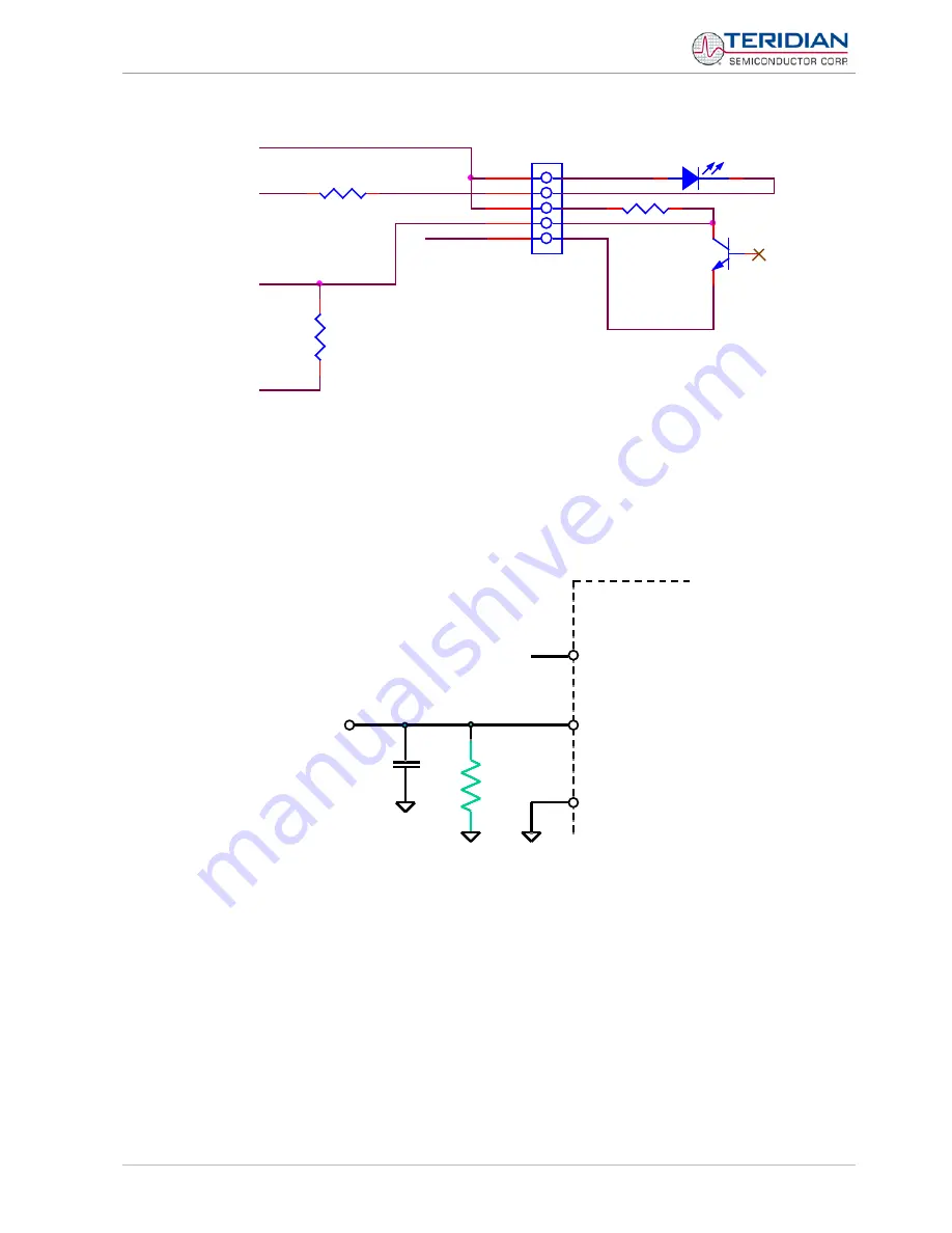
Figure 2-14: Optical Port Circuitry on the Demo Board
2.3.7 RESET AND PB SWITCHES
If not used, the RESET and PB pins should be connected to DGND either directly or via a resistor, as shown
in Figure 2-15. This ensures good EMI performance. If RESET has to be enabled for testing, R
1
has to be
removed.
Figure 2-15: RESET pin, disabled
If the RESET and PB pins are to be used in the battery modes, care must be taken to ensure proper supply
of the associated switches. In most cases, it is sufficient to supply RESET and PB with a voltage from the
battery, as shown in Figure 2-16.
Some of the Demo Boards have dual supply options, since they may be operated with or without a battery.
In these cases, the voltage to the switches may be supplied from two sources: VBAT and V3P3 (see Figure
2-17). In sleep and LCD mode, VBAT supplies voltage to the switch. When the battery is not installed, V3P3
enables the switch in mission and brownout mode.
R79
100
GND
V3P3
OPT_TX
R84
47K
OPT_TX_OUT
1
2
3
4
5
J12
HDR5x1
OPTICAL I/F
OPT_RX
GND
R
1
RESET
71M6521
DGND
0.1µF
100
Ω


