DS_1209F_004
73S1209F Data Sheet
Rev. 1.2
43
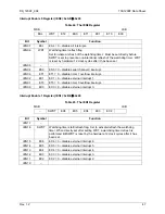
Serial Interface Control Register (S1CON): 0x9B
Å
0x00
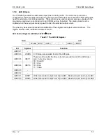
The function of the serial port depends on the setting of the Serial Port Control Register S1CON.
Table 39: The S1CON Register
MSB LSB
SM –
SM21
REN1
TB81
RB81
TI1
RI1
Bit Symbol
Function
S1CON.7
SM
Sets the UART operation mode.
SM Mode Description Baud
Rate
0 A 9-bit
UART variable
1 B 8-bit
UART variable
S1CON.6 –
S1CON.5
SM21
Enables the inter-processor communication feature.
S1CON.4
REN1
If set, enables serial reception. Cleared by software to disable
reception.
S1CON.3
TB81
The 9th transmitted data bit in Mode A. Set or cleared by the MPU,
depending on the function it performs (parity check, multiprocessor
communication etc.).
S1CON.2
RB81
In Mode B, if sm21 is 0, rb81 is the stop bit. Must be cleared by
software.
S1CON.1
TI1
Transmit interrupt flag, set by hardware after completion of a serial
transfer. Must be cleared by software.
S1CON.0
RI1
Receive interrupt flag, set by hardware after completion of a serial
reception. Must be cleared by software.
Multiprocessor operation mode:
The feature of receiving 9 bits in Modes 2 and 3 of Serial Interface 0
or in Mode A of Serial Interface 1 can be used for multiprocessor communication. In this case, the slave
processors have bit SM20 in
set to 1. When the master processor outputs
slave’s address, it sets the 9th bit to 1, causing a serial port receive interrupt in all the slaves. The slave
processors compare the received byte with their network address. If there is a match, the addressed
slave will clear SM20 or SM21 and receive the rest of the message, while other slaves will leave the
SM20 or SM21 bit unaffected and ignore this message. After addressing the slave, the host will output
the rest of the message with the 9th bit set to 0, so no serial port receive interrupt will be generated in
unselected slaves.


