background image

9


Walls: 

Walls of combustible materials must be protected from fire with ceramic tiles 1" thick, or an equivalent non-
combustible material, on fire-proof supports, or with a metal sheet minimum of 0,06" (1.5 mm) on fire-proof 
supports.  

The protection’s height should be from the floor to the level of 10” (250 mm) over the top of stove. 


The minimum clearance from the wall to the nearest surface or side of the stove and flue should be: 

a) clearance from combustible or semi-combustible wall to the stove and flue – not less than 20” (500 mm). 

b) clearance from the wall, protected by a metal sheet, to the stove and flue – not less than 15” (380 mm) 

c) clearance from the non-combustible wall to the stove and flue – not less than 4” (100 mm) 

d) clearance from the firebox door to the nearest wall – not less than 50” (1250 mm) 


Ceiling: 

The clearance between the top of the stove and the ceiling should be not less than 50” (1250 mm). 


The  minimum  clearances  to  combustible  materials  can  be  decreased  by  installing  fire-proof  shields 
between the floor or walls and the stove. Those shields must be installed permanently, if you plan to use 
the installation site periodically. 

Fire-proof shield recommendations 

Ceramic  tiles  1"  (25  mm)  thick,  or  an  equivalent  non-combustible 
material,  on  fire-proof  supports,  or  a  minimum  of  0.06"  (1.5  mm) 
metal sheet on fire-proof supporst 

Floor 


 - clearance to combustible and hard 
combustible 

5.5" (140 mm) 

 - clearance to noncombustible 

at the floor level 

 - additional requirement 

Before  and  under  the  firebox  door  it’s  strictly  recommended  to 
install  a  minimum  of  0.06"  (1.5  mm)  metal  sheet  on  fire-proof 
supports,  sheet  dimensions  20"  x  27  "  (500  mm  x  700  mm),  with 
long side along the stove 

Walls


Ceramic  tiles  1"  (25  mm)  thick,  or  an  equivalent  non-combustible 
material,  on  fire-proof  supports,  a  minimum  of  0.06"  (1.5  mm) 
metal sheet onfire-proof supports, from the floor to the level above 
10” (250 mm) of the stove’s level   

 - clearance to combustible and hard 
combustible 

20” (500 mm) 

 - clearance to a sheet metal on fire-
proof supports 

15” (380 mm) 

 - clearance to non-combustible 

4” (100 mm) 

 - clearance to firebox door 

50” (1250 mm) 

Ceilings 


 - clearance to ceiling 

50” (1250 mm) 

Summary of Contents for INDIGIRKA-2

Page 1: ... installing or operating this equipment 2 Failure to follow these instructions could result in fire or explosion which could cause property damage personal injury or death 3 Improper installation adjustment alteration service or maintenance can cause injury or property damage 4 For Outdoor Use Only Warmth comes from Siberia INSTALLATION AND OPERATION OWNER S MANUAL Made in Russia ...

Page 2: ... termofor ru eng office termofor ru Table of Contents IMPORTANT SAFEGUARDS 3 CHARACTERISTIC FEATURES 4 SPECIFICATIONS AND DIMENSIONS 5 DESCRIPTION AND DESIGN 7 CLEARANCES 8 INSTALLATION 10 OPERATION 12 OPERATION IN ELECTRICITY GENERATING MODE 13 MAINTENANCE 14 MALFUNCTIONS 15 BASICS OF THERMOELECTRICITY 15 PACKAGING AND TRANSPORTATION 16 LIMITED FIVE YEAR WARRANTY 18 This document is protected by ...

Page 3: ...to burn natural wood It is strictly forbidden to use coal and coal briquettes Do not start a fire with vapors chemicals or fluids such as gasoline engine oil alcohol etc Do not touch the stove or its parts while they are hot and educate all children of the danger of a high temperature appliance Children and pets should be supervised when they are in the area close to the burning stove or in the sa...

Page 4: ...tebook a cell phone an iPod or Reader a camera or watch a portable TV or radio It s not very much but in emergency situations it will allow you to use most portable devices you have used before You may want to keep it safe in your backyard just in case The project was developed by Termofor in association with Kryotherm a company based in Saint Petersburg Russia The same types of generators made by...

Page 5: ...27 mm Height 25 7 652 mm Weight 119 lb 54 kg Door size diameter 7 178 mm Firebox volume 1 45 cu ft 41 l Fuel capacity 1 cu ft 30 l Length of logs maximum 14 36 cm Flue size 3 15 80 mm Flue height minimum 10 ft 3 m Number of flue pipes included 9 pcs Area of heating surface 6 5 sq ft 0 6 sq m Output power 50W Output voltage 12V Table 1 Specifications of the Electricity generating heating and cookin...

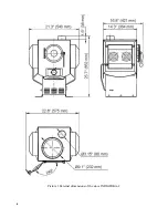
Page 6: ...6 Picture 1 External dimensions of the stove INDIGIRKA 2 ...

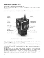
Page 7: ...oxygen in a heated area The grate is made of a sheet of heat resistant high alloy stainless steel 0 12 3 mm thick and is designed to force the burning process and get a powerful high temperature flame Stove components which do not carry a large thermal working load are made of structural steel of 0 06 1 5 mm thick Two Thermoelectric Generators B25 12 further TEG 8 are installed on the side surface...

Page 8: ... 2 Handle in this model line which is designed with handles at the upper part of the stoves Handles are intended for carrying purposes and for protection of expensive thermoelectric generators from the occasional strokes and falls CLEARANCES The minimum clearances to combustible materials can be decreased by installing fire proof shields between the floor or walls and the stove Those shields must ...

Page 9: ...d by installing fire proof shields between the floor or walls and the stove Those shields must be installed permanently if you plan to use the installation site periodically Fire proof shield recommendations Ceramic tiles 1 25 mm thick or an equivalent non combustible material on fire proof supports or a minimum of 0 06 1 5 mm metal sheet on fire proof supporst Floor clearance to combustible and h...

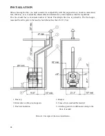
Page 10: ...lations Flue line should have a minimum number of bends The straight flue line is preferable The flue height measured from the grate to the mouth should be not less than 16 5 ft 5 m 1 Flue cap 2 Bracket 3 Metal sheet on fire proof supports 4 Fence of non combustible material 5 Flue heat insulation 6 Attaching points for additional securing to the floor if needed Picture 3 Example of the stove inst...

Page 11: ...lag basalt wool sand etc The distance from the outer surface of the flue without insulation to the rafters roof battens and other parts of the roof of combustible and semi combustible materials should be not less than 10 250 mm And for a non combustible flue insulation not less than 5 130 mm The space between the flue and roof structures of combustible and semi combustible materials should be cove...

Page 12: ...start of operation the stove should be inspected and repaired A malfunctioning stove is not allowed for operation Attention Make sure that no combustibles are in the area close to the stove Be sure the room is adequately ventilated and the flue is unobstructed 1 Place several wads of crushed paper on the firebox floor 2 Lay dry sticks of kindling on top of the paper 3 Pull out the ash drawer to pr...

Page 13: ...ERATING MODE Attention Before start of operation the stove should be inspected and repaired A malfunctioning stove is not allowed for operation Attention Make sure that no combustibles are in the area close to the stove Be sure the room is adequately ventilated and the flue is unobstructed 1 Place several wads of crushed paper on the firebox floor 2 Lay dry sticks of kindling on top of the paper 3...

Page 14: ...e Ash Drawer to provide more air feed MAINTENANCE Replacement of structural elements should be done only by qualified specialists Danger Clean and maintain the stove only after full cooling off For most efficient and safest operation of the stove provide a good working order of the flue system The inner surface of the flue should be as smooth as possible do not contribute to the accumulation of mo...

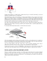
Page 15: ...meter of the flue too short length or the flue being too close to trees or higher buildings Malfunction Cause Removal Malfunction of combustion process Deteriorated draft in the flue pipe Clean the flue pipe Streaks on outer surface of the flue Insufficient tightness of flue joints Seal joints with a heat resistant sealant BASICS OF THERMOELECTRICITY If you are curious about how your stove generat...

Page 16: ...e side of the thermoelectric module is cooled and the other is heated If the heat dissipation from the thermoelectric module s hot side is provided efficiently for example by a heat sink the temperature of the cold side could get down to tens of degrees below the ambient temperature In case the current changes its polarity the hot and cold sides would invert Any power plant produces waste heat whi...

Page 17: ...l your Bill of Sale to us We suggest that you attach your Bill of Sale to this page so that you will have all the information you need in one place should the need for service or information occur Transportation of the stove is allowed only in the original manufacturer packaging by any transport subject to safeguards written on the packaging The stove is painted with heat resistant silicone enamel...

Page 18: ... any incidental or consequential damages caused by defects in the product Adjustments regular maintenance cleaning and temporary repairs or the failure to duplicate the problem in the home is not covered under this warranty This warranty does not extend to or include surface finish on the appliance or terminations door gaskets glass gaskets glass discoloration wool or other ceramic insulating mate...

Page 19: ...s or liability in connection with the sale or use of the appliance In states that do not allow limitations on how long an implied warranty lasts or do not allow exclusion of indirect damage those limitations of exclusions may not apply to you You may also have additional rights not covered in this Limited Five Year Warranty Termofor reserves the right to investigate any and all claims against the ...

Reviews: