24
EOS-EWS_42-53_U161600
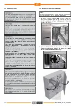
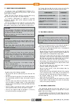
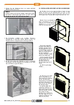
3. Pass the motor cable in the previously installed cable cover
(pos.28).
NOTE
Make sure, at the end of the procedure, you have completely
removed the motor cable from the extractor and that it is intact
and free of cuts and/or deformations.
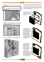
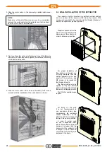
4. Re-close the safety nets and, after having brought the fastening
devices to a horizontal position, tighten the screws to the locking
of the device as required.
5. With the motor cable removed and the safety nets locked,
proceed with the installation of the wall extractor or frame.
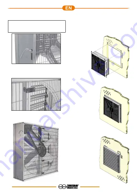
6.3 WALL INSTALLATION OF THE EXTRACTOR
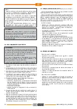
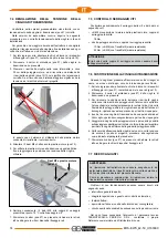
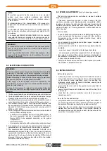
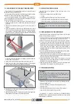
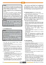
The extractor must be mounted in a perfectly vertical position
and can be fixed to the structure of the room by means of M8
screws (not supplied) to be inserted into the threaded bushes of
which the bodywork is provided (pos.59).
Prepare a square hole in the
wall of 10 mm wider than the
dimensions of the extractor, in
order to allow easy insertion.
For proper installation of
the extractor on the wall, use
of fixing elements that are
easily applicable to the side
panels of the machine using
M8 screws to be inserted in
the threaded inserts.
The fixing profiles can be
applied to top and bottom
panels of the machine through
the use of self-tapping screws.
The FIX kit is available upon
request.
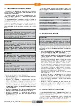
For fixing on the wall,
it is not recommended to
use expansion foam since
compressing the extractor
causes deformation of the
structure and the consequent
failure of the opening shutter.
In case of actual need
for use of expansion foam,
insert the expansion product
between the support and the
bodywork of the extractor for
a length of up to about 20
cm starting from the edge, as
indicated in the figure.
X+10mm
Y+10mm
X
Y
Summary of Contents for EOS 42/0,5
Page 63: ......

