25
EOS-EWS_42-53_U161600
NOTE
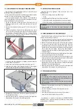
The vertical support to fix the extractor to in an elevated
position must have suitable resistance and stability
characteristics to support the weight and vibrations induced
of the extractor.
The determination of the characteristics of the support is
delegated to the installer and only the latter can assess their
suitability.
It is forbidden to install the extractor on movable supports,
such as doors or shutters, with strength and rigidity, not fit
for purpose.
In no event shall TERMOTECNICA PERICOLI S.R.L. be held
responsible for damage to property and/or persons caused by
installation of one or more extractors on unsuitable supports.
WARNING
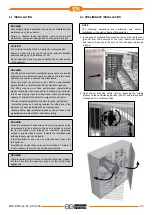
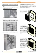
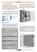
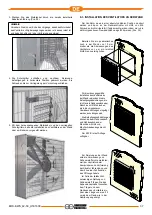
The exhaust fan must be installed so that the cover plates
(pos. 6) can be easily removed to enable maintenance and
cleaning operations.
Avoid any possible obstruction of the holes located on the
lower part of the wallhousing, which guarantee the correct
drainage of the water.
6.4 ELECTRICAL CONNECTION
WARNING
The power supply connection must be made by trained qualified
personnel in compliance with safety regulations currently in
force in the country in which the equipment is being installed.
Before attempting to connect to the mains supply, power down
the power supply line by opening the main switch.
If the supply cord is damaged, it must be replaced by the
manufacturer, its service agent or similarly qualified persons in
order to avoid a hazard.
In case it is necessary to replace the cord please follow the
connections shown in the wiring diagram in the end part of this
manual.
1. The fan is supplied with no electrical actuating and control devices.
2. The label placed under the motor cable outlet indicates the type
of supply voltage for which the motor has been configured.
3. Check that the power supply available at the installation location,
correctly provides the required voltage and frequency values.
4. The installer must provide a control panel that complies with
the requirements of International Electrotechnical Commission
standard IEC 61439 and proper wiring that complies with IEC
60204 and IEC 60364.
5. The following power system protection devices must be installed:
•
Safety lockable isolating switch
•
A Miniature Circuit Breaker (MCB) (correctly-sized referring to
the motor nameplate data) and a possible Residual Current
Device (RCD) (to be assessed depending on the system
configuration).
•
A start/stop switch
•
An emergency stop button with mechanical lock and manual reset.
6. It is necessary to correctly size the cables in relation to the motor
nameplate data, their length and to the installation conditions.
7. The machine shall be properly connected to Earth via a
dedicated yellow/green cable in such a way as to create an
equipotential bonding circuit that is effective against the risk of
electrocution. The choice of whether to install an RCD which will
intervene if there is a discharge to earth is left to the installer
(reference standard IEC 64-8).
6.5 SPEED ADJUSTMENT
(Only for 3-phase type motors)
The fan motor speed can be controlled by means of suitable
frequency converters.
If frequency converters are used, in order to ensure that the
machinery complies with Electromagnetic compatibility (EMC)
requirements replace the cable and the cable gland supplied with
shielded symmetrical cables and EMC cable glands (i.e. cable
glands providing 360 ° bonding between the cable shield and the
motor housing).
You also need:
•
to use shielded symmetrical cables and EMC glands along the
entire line between the frequency converter and the machine,
for example on the converter, possible junction boxes, safety
switches, motor etc...;
•
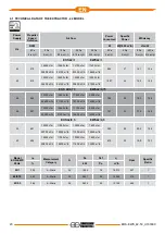
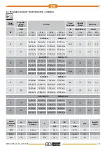
do not exceed the motor/propeller rotation speed indicated in
the technical data table;
•
set the converter so that the speed can be regulated within the
two limits:
- maximum speed - indicated in the technical data table;
- minimum speed - greater than or equal to 50% of the rated speed.
•
the design and sizing of the electrical system are delegated to
the installer or to a deputy; all work must comply with the rules
in force in the destination country.
•
Comply with the provisions laid down in the frequency converter
manufacturer’s installation manual.
6.6 INITIAL START-UP
Before starting the fan:
•
make sure you have not left any object or tool inside the machine;
•
ensure that cement or lime residues have not been deposited
on the blades during installation work; the resulting fan
imbalance would cause to harmful vibrations causing rapid
wear of the propeller bearing;
• ensure that the wire mesh safety guards are securely fitted to
the machine;
•
ensure that staff keep a safe distance (at least 30 metres) from
the machine.
•
check that the electrical protection and safety devices are
operating correctly.
Once the fan has been started:
•
verify that it has been correctly installed checking to see that there is
no unusual vibration and/or noises. if there any of these are present
then switch off the machine, identify the problem and rectify it;
•
check that the fan rotation direction is anticlockwise when
viewed from the fan air inlet side; if the rotation direction is
clockwise and hence erroneous then invert the two wires in the
power line (three-phase motors).
Summary of Contents for EOS 42/0,5
Page 63: ......

