27
EOS-EWS_42-53_U161600
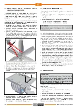
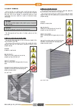
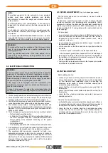
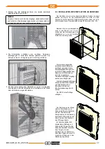
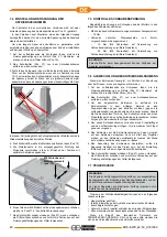
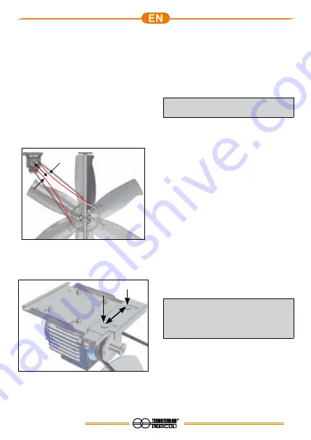
M8 Nuts and motor plate
(pos. 13)
7.4 ADJUSTMENT OF THE BELT TENSION DRIVE
The extractor, in the preassembled versions, comes with correct
tensioning of the drive belt (pos.21).
In the versions to be assembled, the following procedure must be
followed for correct belt tensioning during installation.
To ensure greater duration of the extractor, it is advisable to
check the tensioning of the belt at the end of installation and each
time a maintenance cycle is performed.
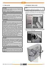
1. On the air inlet side, loosen the screws that secure the net
fastening devices (pos.31), rotate them and open the two nets
(pos.19).
2. Remove the protective casing (pos.27) of the drive belt, if
present.
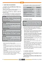
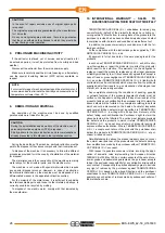
3. Press the branches of the belt in the intermediate zone, about
30 cm from the motor pulley, and if there is a distance between
the branches of the belt of about 12/13 cm, it means that the
tension is correct. If there is a greater distance, it means that
the tension is below the design value.
In this case the the adjustment of slippage system allows the
correct value to be restored.
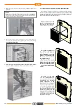
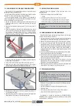
4. Loosen the 2 M8 nuts that secure the motor plate (pos.13).
5. Slide the motor plate in the opposite direction to the propeller
until reaching the position with optimum belt tension.
6. Retighten the 2 M8 nuts to the torque required by section 7.5
“Screw tightness check”.
7.
Refit the casing (pos.27), if present, close the nets again and
finally tighten the screws on the net fixing devices.
7.5 SCREW TIGHTNESS CHECK
Regularly check the tightness of the bolts and nuts in the
following points:
• M8 motor mounting screws, specified torque:
- 18 Nm
•
screw between the pulley and motor, torque required:
- 10 Nm (M6 screws) using threadlocker (medium strength)
- 25 Nm (M8 screws) using threadlocker (medium strength)
CAUTION
Incorrect values in the torque can cause damage to the
equipment!
7.6 REPLACEMENT OF THE DRIVE BELT
When the belt is frayed, with obvious signs of wear, or in the case
of tears, it is necessary to replace it.
1. On the air inlet side, loosen the screws that secure the net fastening
devices (pos.31), rotate them and open the two nets (pos.19).
2. Remove the protective casing (pos.27) of the drive belt, if present.
3. To remove the worn belt, push the branches of the belt in the
intermediate area to the pulleys towards the inside of the fan
(toward the air outlet side) and simultaneously rotate the propeller.
Once freed from the pulleys, remove the belt between a
propeller blade and the orifice by repeating this process for the
other five blades.
4.
Insert a new drive belt between a propeller blade and the orifice,
working accordingly for the other five blades.
5. Fit the belt on the motor pulley and as far as possible on the
driven pulley, then rotate the propeller with force to lift the entire
belt into the groove of the driven pulley.
6.
Check the deflection of the V-belt, if the tension is too low
please adjust. The motor plate position to obtain the deflection
indicated in the preceding paragraph.
7.
Refit the casing (pos.27), if present, close the nets again and
finally tighten the screws on the net fixing devices.
7.7 TROUBLESHOOTING
WARNING
The repairing of the extractor must be performed only by
trained personnel in compliance with safety standards and
requirements set forth in this Manual.
Before any type of repair, isolate the power line by opening
the main switch.
Problems of non-operation may be due to the following causes:
•
the main switch is off;
•
incorrect adjustment or failure of the automatic control;
•
defective fuses;
•
dirt in the propeller and/or the inner ring of the conveyor;
•
open circuit in the connection box or outlet.
If assistance or service is necessary by TERMOTECNICA
PERICOLI S.R.L. technical personnel, contact your local sales
representative or Distributor.
30
cm
12/13 cm
Summary of Contents for EOS 42/0,5
Page 63: ......

