background image

16 


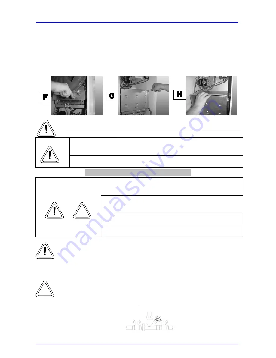
4.  In order to access the combustion chamber: 

  Dismount the expansion tank by removing the fastening screws from the mounting 

brackets (F). 

  Remove the screws (G) and pull out the front housing in order to separate it from the 

lower drawbars (H) (carry out this operation very carefully to avoid damage to the 
refractory panel installed there). 


After any maintenance and/or control operations reset all initial 
adjustment settings.


Before opening the boiler, empty all the components that may contain hot 

water using the appropriate vent holes. 


Warning 

Tighten all the vent openings before carrying out gas pressure readings or 

regulation. 


Preparing the boiler for initial ignition 


Use the externally fitted switch to cut off the power supply to 

the boiler before carrying out any operation. 

To guarantee the safe use of the boiler, the equipment must 
be installed by a qualified registered installer, in accordance 

with the corresponding regulations. 

Do not carry out any operation without previously searching 

for gas leaks with an appropriate device. 


Warning 

Do not carry out any operation without previously checking 

that there are no naked flames or sparks. 


While carrying out the above mentioned operations, only qualified personnel 
must be present in the room where the boiler is installed. 


Before the boiler ignition and functional test, perform the following checks: 


  Pre-loading of expansion tank; 


Fill the water circuits as follows: Open the escape valve fitted in the 
radiators; remove the automatic purge valve cap located on the pump; 
gradually open the boiler inlet cock and close the air purge valve of the 
radiators as soon as water starts to flow out.  Close the inlet cock when the 
water pressure gauge indicates 

1 bar

.


Summary of Contents for Stella

Page 1: ... d d c c ch h ha a am m mb b be e er r r c c co o on n nd d de e en n ns s si i in n ng g g b b bo o oi i il l le e er r r I I In n ns s st t ta a al l ll l la a at t ti i io o on n n M M Ma a ai i in n nt t te e en n na a an n nc c ce e e a a an n nd d d U U Us s se e er r rs s s M M Ma a an n nu u ua a al l l ...

Page 2: ...rther checks 18 19 Operation adjustment and gas flow regulation 20 Boiler Protection Systems 21 Maintenance 22 General concepts 22 Combustion analysis 22 Procedure for emptying the installation 23 Troubleshooting 24 Users Manual 25 General warnings 25 General safety rules 26 Getting to know your boiler 27 Boiler Set up 28 Maintenance 29 Technical Details 30 The following pictograms are shown in so...

Page 3: ...initial ignition maintenance combustion analyses or any other technical operation only a qualified technician must be present near the boiler or in the room where it is installed The boiler is cardboard packed once the packaging is open ensure that the appliance is complete and not damaged Return to manufacturer if the appliance does not fulfil these requisites Keep dangerous packing components st...

Page 4: ...use Damage to the appliance or adjacent objects due to ejected splinters knocks and cuts Risk of personal injury from ejected splinters or fragments dust inhalation impacts cuts punctures scratches noise or vibration Use adequate electrical equipment correctly make sure that the feed cable and the plug are not damaged and that the parts with rotary and reciprocating motions are adequately fixed Ma...

Page 5: ...disconnected pipes or faulty disconnected components Do not carry out any operation without previously checking that there are no naked flames or sparks Explosion or fire due to gas leakage from damaged disconnected pipes or faulty disconnected components Ensure that the discharge and ventilation passages are not obstructed Explosion fire or intoxication due to incorrect ventilation or extraction ...

Page 6: ...ipes carefully to remove any threading and welding residues or dirt that may impair the correct operation of the appliance Check that the boiler is suitable for use with the type of gas available read the instructions on the packing label and the boiler data plate Check that the flue is not blocked or connected to any other discharge pipe except when the flue has been designed for other uses compl...

Page 7: ...oiler The boiler has been designed to be installed on a wall and cannot be installed on a base or on the floor If the boiler is built in the minimum clearances that guarantee access to all boiler components must be satisfied Dimensions and templates 1 Heating system return 3 4 2 Cold water inlet 3 Gas inlet 3 4 4 Hot water outlet 1 2 5 Heating system flow 3 4 Minimum clearances Comply with the min...

Page 8: ...ating setting Remove the safety screw C see Page 14 ELECTRIC DIAGRAM and rotate the internal plastic screw counter clockwise a few turns until when turning the pressure does not decrease any further At this point act on D until the minimum pressure is reached as indicated in the data table for the gas used page 30 in this booklet Once the minimum pressure is adjusted the maximum pressure is adjust...

Page 9: ... and could result in discomfort for users Water connections Warning Before connecting water pipes clean the appliance carefully to remove any residues or dirt that may impair the correct operation of the boiler Make sure that the expansion tank capacity is suitable for the water content of the boiler Warning To avoid possible short circuits install the feed cables and if supplied the room thermost...

Page 10: ...n old one the whole fume extraction and flue exhaust system must also be replaced Ensure that the discharge and ventilation passages are not obstructed Warning Ensure that the flue exhaust connections do not leak This sealed chamber boiler must only be installed together with a flue exhaust device supplied by the boiler manufacturer as required by UNI 7129 and 7131 standards This kit is supplied s...

Page 11: ...e appropriate adapter to the flue spigot 2 Fasten the metal clamp and the neoprene rectangular gasket using the screws 3 Correctly position the circular silicone gasket 4 Loosen the screws to remove one of the two upper closing plates 5 Screw down the appropriate inlet stub pipe 6 Insert the silicone gasket 7 Attach the kit adapted to the system to be used To attach or remove the diaphragm follow ...

Page 12: ...e the same diameter 80 mm 2 When attaching the curve to the inlet and or flue systems the performance calculation must include the equivalent length for each system 3 The flue duct must protrude at least 0 5 m from the rooftop when it is located on the side opposite to the inlet duct this is not compulsory when the flue and the inlet ducts are on the same side of the building A 39 mm diaphragm can...

Page 13: ...of the electric connections The manufacturer shall not be held responsible for damage resulting from lack of earthing or power failures Ensure the system is compatible with the maximum boiler output as indicated on the data plate Check that the cable sizes are the correct ones no smaller than 1 5 mm2 A correct and efficient earthing guarantees a safe appliance Important The connections to the main...

Page 14: ...o reach the terminal board 3 Make all connections according to the indications in the diagram of the terminal board remember to thread the cables through the appropriate fairleads remove the attached flap to connect the room thermostat 4 Fasten the fairleads and replace the flap door Warning Do not connect the mains cable 230 V AC to the room thermostat Doing this may damage the electronic board ...

Page 15: ...14 Electrical Layout Screw A pressure inlet ...

Page 16: ...astening springs by pressing them with a screwdriver and remove the front panel by pulling it out slightly and lifting it in order to release it from the two upper draw pins B 2 To access the control panel Pull out the box C to have access to the setting switch D this method is only to be used when the power supply has been cut off pay attention to the boiler wiring mainly when refitting the box i...

Page 17: ...rying out any operation To guarantee the safe use of the boiler the equipment must be installed by a qualified registered installer in accordance with the corresponding regulations Do not carry out any operation without previously searching for gas leaks with an appropriate device Warning Do not carry out any operation without previously checking that there are no naked flames or sparks While carr...

Page 18: ... properly earthed Check the electrical connections of the external components thermostats remote control etc if supplied When loading the system check that the plug of the automatic air purge valve located on the pump is loose Make sure that the pump is not blocked if so remove the front plug to unblock the driving shaft with a screwdriver If pressure is lower than 1 bar feed more water into the c...

Page 19: ...yout provides indications for identifying all the necessary controls used to start up the boiler therefore Adjust the boiler thermostat 1 and the mains water thermostat 2 located on the control panel Power the boiler by opening the external switch Set the selector 3 located on the control panel at the winter setting and check that the ON pilot light green LED on the control panel lights up Warning...

Page 20: ...ED flashing of all ON quick and 3 sec OFF The appliance undergoes the ignition phase and once firing it continues functioning until the preset temperature is reached Ignition and the following stops shall take place automatically according to the preset temperature If the safety thermostat is activated as indicated by the corresponding LED see Chart No 1 the boiler goes through a thermal safety st...

Page 21: ...ttom of the furnace without disconnecting it Return the external switch to the ON 1 position and turn the furnace on in the heating setting Remove the safety screw C see Page 14 ELECTRIC DIAGRAM and rotate the internal plastic screw counter clockwise a few turns until when turning the pressure does not decrease any further At this point act on D until the minimum pressure is reached as indicated i...

Page 22: ...operly therefore indicating that The system pressure is appropriate The boiler is electrically powered Gas is adequately supplied 4 Circulator protection in order to protect the circulator and avoid lock out the boiler activates the circulator for 30 seconds every 24 hours after the last intake and or operation 5 Protection of electrical shunting switch in order to protect the valve and avoid lock...

Page 23: ... reset all initial adjustment settings Before opening the boiler empty all the components that may contain hot water using the appropriate vent holes In order to remove scale deposits as indicated in the safety instructions of the product used ventilate the room and wear proper protective clothing Also avoid mixing several products and protect the surrounding equipment and objects Tighten all the ...

Page 24: ...ose the mains water cock 2 Open all the hot and cold water taps 3 Empty the system from the lowest points if present Before opening the boiler empty all the components that may contain hot water using the appropriate vent holes In order to remove scale deposits as indicated in the safety instructions of the product used ventilate the room and wear proper protective clothing Also avoid mixing sever...

Page 25: ...24 ...

Page 26: ...ce objects plants and animals General Warning This manual must be kept to hand and protected against the effects of atmospheric agents Scheduled and preventive maintenance operations are essential in order to guarantee correct and safe functioning to avoid excessive consumption and to reduce the emission of contaminating agents Maintenance must be carried out by Qualified Personnel according to th...

Page 27: ...eric agents if it is installed outdoors place it in a sheltered area or apply protection coating Do not cover and or obstruct and or reduce the size of the ventilation openings of the room where the appliance is installed as they are essential in order to ensure correct combustion and to avoid stagnation of toxic explosive or potentially hazardous gas mixtures If there are water leaks cut off elec...

Page 28: ...em sensor OFF ON L ON L Failure of NTC sanitary system sensor ON L ON L OFF Activation of safety thermostat during sanitary function OFF ON L1 ON L Boiler in central heating phase OFF OFF ON L Boiler in domestic hot water cycle ON L OFF OFF Boiler in anti frost cycle ON L ON L 1 OFF Stand by ON L 1 OFF OFF Stand by during heating phase ON OFF ON Stand by during summer phase ON OFF OFF Remote contr...

Page 29: ...s been finished continue as follows Set the selector 3 located on the control panel at the winter setting to enable both the heating system and the hot water system Set the selector 3 at the summer setting to enable only the production of domestic hot water The appliance undergoes the ignition phase and once firing it continues functioning until the preset temperature is reached Ignition and the f...

Page 30: ...ce Maintenance reduces excessive use and contaminating emissions and it also ensures long lasting product reliability Maintenance must be carried out by Qualified Personnel according to the provisions of the regulations in force The log book must be completed after all servicing operations as stated by the regulations in force ...

Page 31: ...C 35 55 Hot water flow T 25 C 13 Hot water flow T 35 C 9 3 Minimum hot water extraction l 2 3 Max pressure hot water circuit bar 8 Expansion tank capacity l 7 7 Expansion tank pre load pressure bar 1 1 Heating system maximum pressure bar 3 3 G20 methane gas nominal pressure mbar 20 20 Min pressure at G20 methane gas nozzles mbar 2 6 2 6 Max pressure at G20 methane gas nozzles mbar 11 3 11 3 G30 G3...

Reviews: